Toyota Tacoma (2015-2018) Service Manual: Stop Light Control Relay Malfunction (C1380)
DESCRIPTION
The skid control ECU (brake actuator assembly) inputs the stop light switch signal and detect the status of the brake operation.
|
DTC No. |
Detection Item |
DTC Detection Condition |
Trouble Area |
|---|---|---|---|
|
C1380 |
Stop Light Control Relay Malfunction |
Either of the following is detected:
|
|
HINT:
DTC will be output when conditions for either of the patterns in the table above are met.
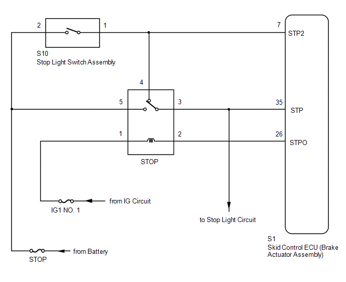
WIRING DIAGRAM
CAUTION / NOTICE / HINT
NOTICE:
- When replacing the skid control ECU (brake actuator assembly), perform
calibration (See page
.gif) ).
). - Inspect the fuses for circuits related to this system before performing the following inspection procedure.
HINT:
When DTC C1425 is output together with DTC C1380, inspect and repair the trouble
areas indicated by DTC C1425 first (See page ).
PROCEDURE
|
1. |
CHECK STOP LIGHT OPERATION |
(a) Check that the stop lights come on when the brake pedal is depressed and go off when the brake pedal is released.
OK:
|
Condition |
Illumination Condition |
|---|---|
|
Brake pedal depressed. |
On |
|
Brake pedal released. |
Off |
| NG | .gif) |
INSPECT STOP LIGHT CIRCUIT |
|
.gif)
|
2. |
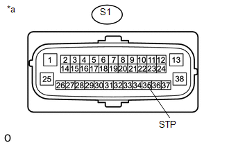
CHECK HARNESS AND CONNECTOR (STP TERMINAL) |
(a) Make sure that there is no looseness at the locking part and the connecting part of the connectors.
(b) Turn the ignition switch off.
(c) Disconnect the skid control ECU (brake actuator assembly) connector.
|
(d) Measure the voltage according to the value(s) in the table below. Standard Voltage:
|
|
| NG | |
REPAIR OR REPLACE HARNESS OR CONNECTOR (STP CIRCUIT) |
|
|
3. |
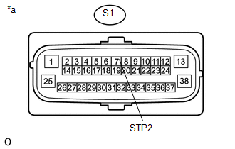
CHECK HARNESS AND CONNECTOR (STP2 TERMINAL) |
|
(a) Measure the voltage according to the value(s) in the table below. Standard Voltage:
|
|
| NG | |
REPAIR OR REPLACE HARNESS OR CONNECTOR (STP2 CIRCUIT) |
|
|
4. |
PERFORM ACTIVE TEST USING TECHSTREAM (STOP LIGHT RELAY) |
(a) Reconnect the S1 skid control ECU (brake actuator assembly) connector.
(b) Connect the Techstream to the DLC3.
(c) Start the engine.
(d) Turn the Techstream on.
(e) Enter the following menus: Chassis / ABS/VSC/TRAC / Active Test.
ABS/VSC/TRAC|
Tester Display |
Measurement Item |
Control Range |
Diagnostic Note |
|---|---|---|---|
|
Stop Light Relay |
Stop Light Relay |
Relay ON/OFF |
Stop lights come on Vehicle condition: Vehicle stopped |
(f) While performing the Active Test, check the illumination condition of the stop lights and "Stop Light Relay Output" in the Data List.
ABS/VSC/TRAC|
Tester Display |
Measurement Item |
Normal Condition |
Diagnostic Note |
|---|---|---|---|
|
Stop Light Relay |
Stop Light Relay |
OFF: Relay output off (Stop lights off) ON: Relay output on (Stop lights on) |
- |
|
Result |
Proceed to |
|---|---|
|
When Active Test performed, Data List item changes between ON and OFF and stop lights turn on and off |
A |
|
When Active Test performed, Data List item changes between ON and OFF, but stop lights do not turn on |
B |
| B | |
GO TO STEP 6 |
|
|
5. |
RECONFIRM DTC |
(a) Turn the ignition switch off.
(b) Clear the DTCs (See page
).
(c) Start the engine.
(d) Perform a road test.
(e) Check if the same DTC is output (See page
).
|
Result |
Proceed to |
|---|---|
|
DTC C1380 is not output |
A |
|
DTC C1380 is output |
B |
| A | |
USE SIMULATION METHOD TO CHECK |
| B | |
REPLACE BRAKE ACTUATOR ASSEMBLY |
|
6. |
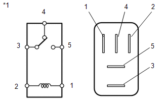
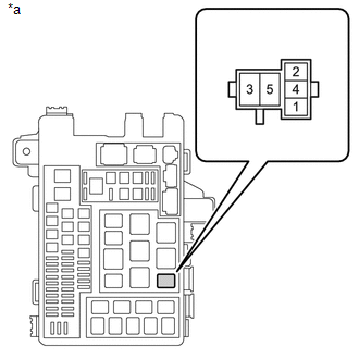
INSPECT STOP LIGHT CONTROL RELAY (STOP RELAY) |
(a) Remove the STOP relay from the engine room relay block.
|
(b) Measure the resistance according to the value(s) in the table below. Standard Resistance:
|
|
| NG | |
REPLACE STOP LIGHT CONTROL RELAY (STOP RELAY) |
|
|
7. |
CHECK TERMINAL VOLTAGE (STOP LIGHT POWER SOURCE TERMINAL) |
|
(a) Measure the voltage according to the value(s) in the table below. Standard Voltage:
|
|
| NG | |
REPAIR OR REPLACE HARNESS OR CONNECTOR |
|
|
8. |
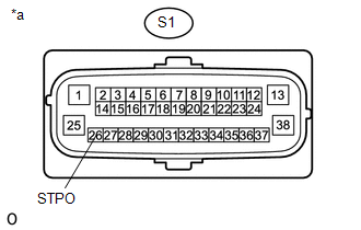
CHECK HARNESS AND CONNECTOR (STPO TERMINAL) |
(a) Install the stop light control relay (STOP Relay).
(b) Make sure that there is no looseness in the locking part and connecting part of the connector.
(c) Disconnect the S1 skid control ECU (brake actuator assembly) connector.
(d) Turn the ignition switch to ON.
|
(e) Measure the voltage according to the value(s) in the table below. Standard Voltage:
|
|
| OK | |
REPLACE BRAKE ACTUATOR ASSEMBLY |
| NG | |
REPAIR OR REPLACE HARNESS OR CONNECTOR (STPO CIRCUIT) |
 Diameter of the Tire is not Uniform (C1337)
DESCRIPTION
The skid control ECU (brake actuator assembly) measures the speed of each wheel
by receiving signals from the speed sensors. These signals are used for recognizing
whether all 4 wheel ...
 Acceleration Sensor Power Supply Voltage Malfunction (C1381)
DESCRIPTION
The skid control ECU (brake actuator assembly) receives signals from the yaw
rate and acceleration sensor (airbag sensor assembly) via the CAN communication
system.
The airbag sensor ...
Other materials:
Power Outlet Socket(for Front Side)
Components
COMPONENTS
ILLUSTRATION
Removal
REMOVAL
PROCEDURE
1. REMOVE INSTRUMENT PANEL LOWER CENTER FINISH PANEL
(See page )
2. REMOVE NO. 1 POWER OUTLET SOCKET ASSEMBLY
(a) Using a screwdriver with its tip wrapped in protective tape, disengage
the 2 claws to remove t ...
No Answer-Back
DESCRIPTION
In some cases, wireless door lock control functions are normal but the hazard
warning light and/or wireless door lock buzzer answer-back function(s) does not
operate. In such cases, hazard warning light and wireless door lock buzzer signal
outputs from the main body ECU (multiplex ...
4WD ECU Malfunction (P163B)
DESCRIPTION
This DTC is output when a malfunction is detected in the 4 wheel drive control
ECU internal circuit.
DTC No.
Detection Item
DTC Detection Condition
Trouble Area
P163B
4WD ECU Malfunction
Dia ...
