Toyota Tacoma (2015-2018) Service Manual: Acceleration Sensor Power Supply Voltage Malfunction (C1381)
DESCRIPTION
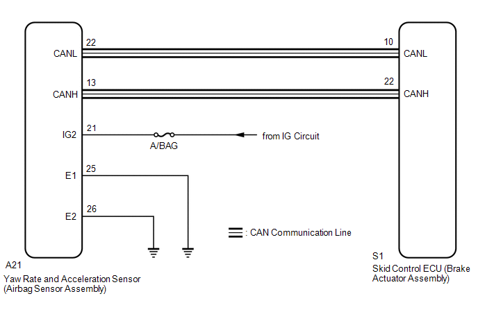
The skid control ECU (brake actuator assembly) receives signals from the yaw rate and acceleration sensor (airbag sensor assembly) via the CAN communication system.
The airbag sensor assembly has a built-in acceleration sensor and detects the vehicle condition.
If there is trouble in the bus lines between the acceleration sensor (airbag sensor assembly) and the CAN communication system, the DTC U0124 (Lost Communication with Lateral Acceleration Sensor Module) is output.
These DTCs are also output when calibration has not been completed.
|
DTC No. |
Detection Item |
DTC Detection Condition |
Trouble Area |
|---|---|---|---|
|
C1381 |
Acceleration Sensor Power Supply Voltage Malfunction |
At a vehicle speed of more than 3 km/h (2 mph), the acceleration sensor power source malfunction signal is received for 10 seconds or more. |
|
WIRING DIAGRAM
CAUTION / NOTICE / HINT
NOTICE:
- When replacing the skid control ECU (brake actuator assembly), perform
zero point calibration and store system information (See page
.gif) ).
).
- When replacing the yaw rate and acceleration sensor (airbag sensor assembly),
perform zero point calibration and store system information (See page
).
- Inspect the fuses for circuits related to this system before performing the following inspection procedure.
PROCEDURE
|
1. |
CHECK TERMINAL VOLTAGE (IG2 TERMINAL) |
NOTICE:
- After turning the ignition switch off, waiting time may be required
before disconnecting the cable from the battery terminal. Therefore, make
sure to read the disconnecting the cable from the battery terminal notice
before proceeding with work (See page ).
- When disconnecting the cable, some systems need to be initialized after
the cable is reconnected (See page
).
(a) Turn the ignition switch off.
(b) Disconnect the cable from the negative (-) battery terminal, and wait for at least 90 seconds.
(c) Make sure that there is no looseness at the locking part and the connecting part of the connector.
|
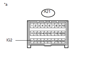
(d) Disconnect the A21 yaw rate and acceleration sensor (airbag sensor assembly) connector. |
|
(e) Connect the cable to the negative (-) battery terminal, and wait for at least 2 seconds.
(f) Turn the ignition switch to ON.
(g) Operate all the components of the electrical system (defogger, wipers, headlights, heater blower, etc.).
(h) Measure the voltage according to the value(s) in the table below.
Standard Voltage:
|
Tester Connection |
Switch Condition |
Specified Condition |
|---|---|---|
|
A21-21 (IG2) - Body ground |
Ignition switch ON |
11 to 14 V |
|
*a |
Front view of wire harness connector (to Yaw Rate and Acceleration Sensor [Airbag Sensor Assembly]) |
| NG | .gif) |
REPAIR OR REPLACE HARNESS OR CONNECTOR (IG2 CIRCUIT) |
|
.gif)
|
2. |
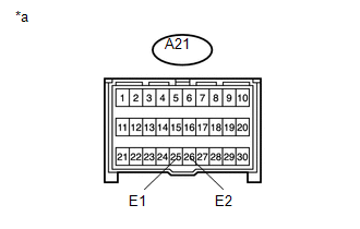
CHECK HARNESS AND CONNECTOR (GND TERMINAL) |
(a) Turn the ignition switch off.
|
(b) Measure the resistance according to the value(s) in the table below. Standard Resistance:
HINT: If troubleshooting has been carried out according to the Problem Symptoms
Table, refer back to the table and proceed to the next step (See page
|
|
| NG | |
REPAIR OR REPLACE HARNESS OR CONNECTOR (GND CIRCUIT) |
|
|
3. |
RECONFIRM DTC |
(a) Reconnect the A21 yaw rate and acceleration sensor (airbag sensor assembly) connector.
(b) Clear the DTC (See page
).
(c) Turn the ignition switch off.
(d) Start the engine.
(e) Perform a road test.
(f) Check if the same DTC is recorded (See page
).
|
Result |
Proceed to |
|---|---|
|
DTC C1381 is not output |
A |
|
DTC C1381 is output |
B |
| A | |
USE SIMULATION METHOD TO CHECK |
| B | |
REPLACE AIRBAG SENSOR ASSEMBLY |
 Stop Light Control Relay Malfunction (C1380)
DESCRIPTION
The skid control ECU (brake actuator assembly) inputs the stop light switch signal
and detect the status of the brake operation.
DTC No.
Detection Item
...
 Front Speed Sensor RH Malfunction (C1401,C1402)
DESCRIPTION
The speed sensor detects wheel speed and sends the appropriate signals to the
skid control ECU (brake actuator assembly). These signals are used for brake control.
The speed sensor rot ...
Other materials:
Steering Pad Switch Circuit
DESCRIPTION
This circuit sends an operation signal from the steering pad switch assembly
to the radio and display receiver assembly.
If there is an open in the circuit, the audio system cannot be operated using
the steering pad switch assembly.
If there is a short in the circuit, the same con ...
Installation
INSTALLATION
PROCEDURE
1. SET NO. 1 CYLINDER TO TDC/COMPRESSION
2. INSTALL CAMSHAFT TIMING GEAR BOLT
NOTICE:
There are different types of camshaft timing gear bolts. Make sure to check the
identification mark to determine the tightening torque.
*a
Identification Ma ...
Data List / Active Test
DATA LIST / ACTIVE TEST
1. DATA LIST
HINT:
Using the Techstream to read the Data List allows the values or states of switches,
sensors, actuators and other items to be read without removing any parts. This non-intrusive
inspection can be very useful because intermittent conditions or signals ...
