Toyota Tacoma (2015-2018) Service Manual: Automatic Light Control Sensor
Components
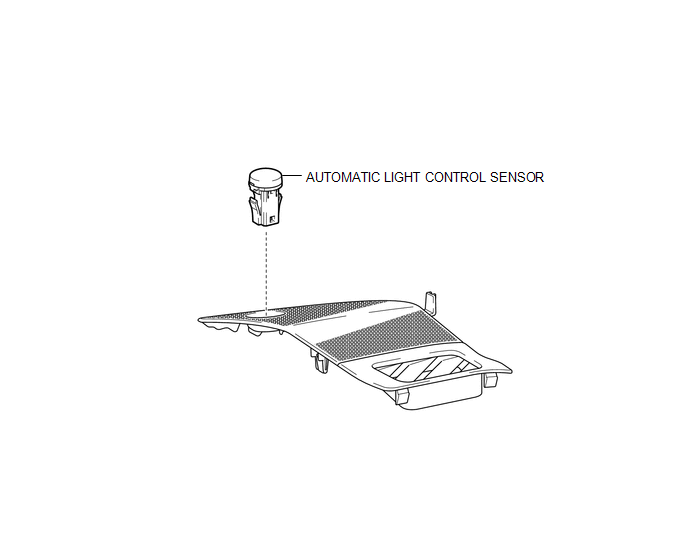
COMPONENTS
ILLUSTRATION
Installation
INSTALLATION
PROCEDURE
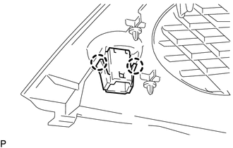
1. INSTALL AUTOMATIC LIGHT CONTROL SENSOR
(a) Engage the 2 claws to install the automatic light control sensor.
2. INSTALL NO. 2 INSTRUMENT PANEL SPEAKER PANEL SUB-ASSEMBLY
(See page .gif) )
)
On-vehicle Inspection
ON-VEHICLE INSPECTION
PROCEDURE
1. REMOVE NO. 2 INSTRUMENT PANEL SPEAKER PANEL SUB-ASSEMBLY
(See page .gif) )
)
2. INSPECT AUTOMATIC LIGHT CONTROL SENSOR
(a) Check the voltage.
|
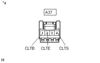
(1) Measure the voltage according to the value(s) in the table below. Text in Illustration
Standard Voltage:
If the result is not as specified, repair or replace the wire harness. |
|
(2) Measure the resistance according to the value(s) in the table below.
Standard Resistance:
|
Tester Connection |
Condition |
Specified Condition |
|---|---|---|
|
A37-2 (CLTE) - Body ground |
Always |
Below 1 Ω |
If the result is not as specified, repair or replace the wire harness.
(b) Connect the connector.
|
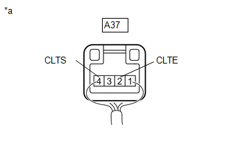
(c) Connect an oscilloscope to the automatic light control sensor connector. Text in Illustration
|
|
|
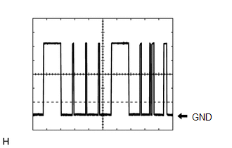
(d) Check the waveform. :
HINT: The communication waveform changes according to the surrounding brightness. If the result is not as specified, replace the automatic light control sensor. |
|
3. INSTALL NO. 2 INSTRUMENT PANEL SPEAKER PANEL SUB-ASSEMBLY
(See page )
Removal
REMOVAL
PROCEDURE
1. REMOVE NO. 2 INSTRUMENT PANEL SPEAKER PANEL SUB-ASSEMBLY
(See page .gif) )
)
2. REMOVE AUTOMATIC LIGHT CONTROL SENSOR
|
(a) Disengage the 2 claws to remove the automatic light control sensor. |
|
 Lighting
...
 Cargo Light
Components
COMPONENTS
ILLUSTRATION
Removal
REMOVAL
PROCEDURE
1. REMOVE ROOF HEADLINING ASSEMBLY
for Double Cab:
(See page
)
for Access Cab:
(See page
)
...
Other materials:
Installation
INSTALLATION
PROCEDURE
1. INSTALL WATER INLET WITH THERMOSTAT SUB-ASSEMBLY
(a) Install a new gasket to the water inlet with thermostat sub-assembly.
(b) Install the water inlet with thermostat sub-assembly to the timing chain
cover assembly with the 2 bolts and nut.
Torque:
10 N·m {102 kgf ...
Components
COMPONENTS
ILLUSTRATION
ILLUSTRATION
ILLUSTRATION
ILLUSTRATION
ILLUSTRATION
ILLUSTRATION
ILLUSTRATION
...
Precaution
PRECAUTION
HANDLING PRECAUTION FOR CRUISE CONTROL SYSTEM
(a) Turn the cruise control system off using the cruise control main switch (ON-OFF
button) when not using the cruise control system.
(b) Be careful as the vehicle speed increases when driving downhill with the
cruise control system con ...
