Toyota Tacoma (2015-2018) Service Manual: Power Outlet Socket(for Rear Side)
Components
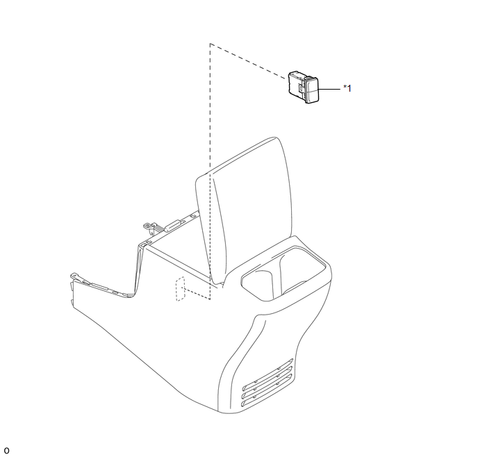
COMPONENTS
ILLUSTRATION
|
*1 |
USB CHARGER SOCKET |
- |
- |
Removal
REMOVAL
PROCEDURE
1. REMOVE REAR CONSOLE BOX ASSEMBLY
Click here .gif)
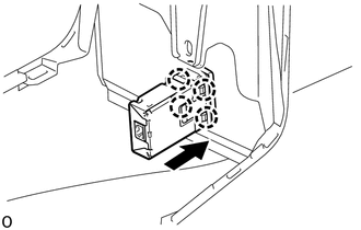
2. REMOVE USB CHARGER SOCKET
|
(a) Disengage the 4 claws to remove the USB charger socket. |
|
Installation
INSTALLATION
PROCEDURE
1. INSTALL USB CHARGER SOCKET
(a) Engage the 4 claws to install the USB charger socket.
2. INSTALL REAR CONSOLE BOX ASSEMBLY
Click here .gif)
 Power Outlet Socket(for Front Side)
Components
COMPONENTS
ILLUSTRATION
Removal
REMOVAL
PROCEDURE
1. REMOVE INSTRUMENT PANEL LOWER CENTER FINISH PANEL
(See page )
2. REMOVE NO. 1 POWER OUTLET SOCKET ASSEMBLY
(a ...
 Rear Power Outlet Socket
Components
COMPONENTS
ILLUSTRATION
ILLUSTRATION
Installation
INSTALLATION
PROCEDURE
1. INSTALL POWER OUTLET SOCKET ASSEMBLY
(a) Install the clamp.
(b) Connect the connector.
...
Other materials:
GPS Mark is not Displayed
PROCEDURE
1.
CHECK CABIN
(a) Check the cabin for any object that might interrupt radio reception or additional
devices which use radio waves on the instrument panel. If such an object exists,
remove it and check if the GPS mark reappears.
HINT:
The GPS uses ex ...
Door Control Receiver
Components
COMPONENTS
ILLUSTRATION
Removal
REMOVAL
PROCEDURE
1. REMOVE ROOF HEADLINING ASSEMBLY (for Double Cab)
(See page )
2. REMOVE ROOF HEADLINING ASSEMBLY (for Access Cab)
(See page )
3. REMOVE DOOR CONTROL RECEIVER (w/o Tire Pressure Warning System)
(a) Disconne ...
Personal Light Assembly
Components
COMPONENTS
ILLUSTRATION
Installation
INSTALLATION
PROCEDURE
1. INSTALL MAP LIGHT BULB
(a) Install the 2 map light bulbs to the 2 map light sockets.
(b) Turn the 2 map light sockets with 2 map light bulbs in the direction
indicated by the arrow shown in the ill ...
