Toyota Tacoma (2015-2018) Service Manual: Sliding Roof ECU Communication Stop (B1273)
DESCRIPTION
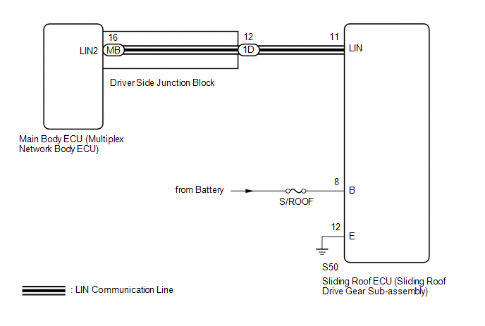
This DTC is stored when LIN communication between the sliding roof ECU (sliding roof drive gear sub-assembly) and main body ECU (multiplex network body ECU) stops for 10 seconds or more.
|
DTC No. |
DTC Detection Condition |
Trouble Area |
|---|---|---|
|
B1273 |
No communication between sliding roof ECU (sliding roof drive gear sub-assembly) and main body ECU (multiplex network body ECU) for 10 seconds or more. |
|
WIRING DIAGRAM
CAUTION / NOTICE / HINT
NOTICE:
- Inspect the fuses for circuits related to this system before performing the following inspection procedure.
- If the main body ECU (multiplex network body ECU) is replaced, refer
to Registration (See page
.gif) )
) - When the sliding roof ECU (sliding roof drive gear sub-assembly) is
replaced or removed and reinstalled, it requires initialization (See page
).
PROCEDURE
|
1. |
INSPECT DRIVER SIDE JUNCTION BLOCK |
(a) Remove the driver side junction block (See page
).
(b) Remove the main body ECU (multiplex network body ECU) from the driver side junction block.
(c) Measure the resistance according to the value(s) in the table below.
Standard Resistance:
|
Tester Connection |
Condition |
Specified Condition |
|---|---|---|
|
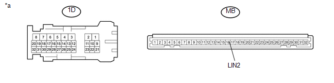
1D-12 - MB-16 (LIN2) |
Always |
Below 1 Ω |
|
*a |
Component without harness connected (Driver Side Junction Block) |
- |
- |
HINT:
This inspection is to check the LIN line in the driver side junction block that connects the wire harness to the built-in main body ECU (multiplex network body ECU).
| NG | .gif) |
REPLACE DRIVER SIDE JUNCTION BLOCK |
|
.gif)
|
2. |
CHECK HARNESS AND CONNECTOR (DRIVER SIDE JUNCTION BLOCK - SLIDING ROOF ECU (SLIDING ROOF DRIVE GEAR SUB-ASSEMBLY)) |
(a) Disconnect the 1D driver side junction block connector.
(b) Disconnect the S50 sliding roof ECU (sliding roof drive gear sub-assembly) connector.
(c) Measure the resistance according to the value(s) in the table below.
Standard Resistance:
|
Tester Connection |
Condition |
Specified Condition |
|---|---|---|
|
1D-12 - S50-11 (LIN) |
Always |
Below 1 Ω |
|
1D-12 or S50-11 (LIN) - Body ground |
Always |
10 kΩ or higher |
| NG | |
REPAIR OR REPLACE HARNESS OR CONNECTOR |
|
|
3. |
CHECK HARNESS AND CONNECTOR (SLIDING ROOF ECU (SLIDING ROOF DRIVE GEAR SUB-ASSEMBLY) - POWER SOURCE CIRCUIT) |
(a) Disconnect the S50 sliding roof ECU (sliding roof drive gear sub-assembly) connector.
(b) Measure the voltage according to the value(s) in the table below.
Standard Voltage:
|
Tester Connection |
Condition |
Specified Condition |
|---|---|---|
|
S50-8 (B) - S50-12 (E) |
Always |
11 to 14 V |
(c) Measure the resistance according to the value(s) in the table below.
Standard Resistance:
|
Tester Connection |
Condition |
Specified Condition |
|---|---|---|
|
S50-12 (E) - Body ground |
Always |
Below 1 Ω |
| NG | |
REPAIR OR REPLACE HARNESS OR CONNECTOR |
|
|
4. |
REPLACE SLIDING ROOF ECU (SLIDING ROOF DRIVE GEAR SUB-ASSEMBLY) |
(a) Replace the sliding roof ECU (sliding roof drive gear sub-assembly) (See
page ).
|
|
5. |
CHECK DTC OUTPUT |
(a) Clear the DTCs (See page ).
(b) Recheck for DTCs.
OK:
DTC B1273 is not output.
| OK | |
END (SLIDING ROOF ECU (SLIDING ROOF DRIVE GEAR SUB-ASSEMBLY WAS DEFECTIVE) |
| NG | |
REPLACE MAIN BODY ECU (MULTIPLEX NETWORK BODY ECU) |
 Diagnostic Trouble Code Chart
DIAGNOSTIC TROUBLE CODE CHART
Main Body ECU (Multiplex Network Body ECU)
DTC Code
Detection Item
See page
B1206
P/W Master Switch Communi ...
 Driver Side Door ECU Communication Stop (B2321)
DESCRIPTION
This DTC is stored when LIN communication between the front power window regulator
motor assembly LH and main body ECU (multiplex network body ECU) stops for 10 seconds
or more.
...
Other materials:
Freeze Frame Data
FREEZE FRAME DATA
1. FREEZE FRAME DATA
(a) Whenever a meter DTC is detected, the combination meter assembly stores the
current vehicle state as freeze frame data.
2. CHECK FREEZE FRAME DATA
(a) Connect the Techstream to the DLC3.
(b) Turn the ignition switch to ON.
(c) Turn the Techstream on ...
Installation
INSTALLATION
PROCEDURE
1. INSTALL VACUUM WARNING SWITCH ASSEMBLY (for 2GR-FKS)
Click here
2. INSTALL BRAKE VACUUM CHECK VALVE ASSEMBLY (for 2TR-FE)
(a) Install a new grommet onto the brake booster assembly.
(b) Install the vacuum check val ...
Main Switch Illumination Circuit
DESCRIPTION
When the light control switch is turned to the tail or head position, this circuit
sends an illumination signal to the wireless charger main switch (mobile wireless
charger switch). Based on this signal, the wireless charger main switch (mobile
wireless charger switch) is illumina ...
