Toyota Tacoma (2015-2018) Service Manual: Pattern Select Switch
Components
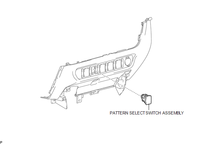
COMPONENTS
ILLUSTRATION
Removal
REMOVAL
PROCEDURE
1. REMOVE INSTRUMENT PANEL LOWER CENTER FINISH PANEL
(See page .gif) )
)
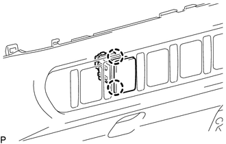
2. REMOVE PATTERN SELECT SWITCH ASSEMBLY
|
(a) Detach the 2 claws to remove the pattern select switch assembly from the instrument panel lower center finish panel. |
|
Inspection
INSPECTION
PROCEDURE
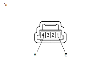
1. INSPECT PATTERN SELECT SWITCH ASSEMBLY
|
(a) Measure the resistance according to the value(s) in the table below. Text in Illustration
Standard Resistance:
If the result is not as specified, replace the pattern select switch assembly. |
|
Installation
INSTALLATION
PROCEDURE
1. INSTALL PATTERN SELECT SWITCH ASSEMBLY
(a) Attach the 2 claws to install the pattern select switch assembly to the instrument panel lower center finish panel.
2. INSTALL INSTRUMENT PANEL LOWER CENTER FINISH PANEL
(See page .gif) )
)
 Installation
INSTALLATION
PROCEDURE
1. INSTALL PARK/NEUTRAL POSITION SWITCH
HINT:
Make sure that the manual valve lever shaft has not been rotated prior to installing
the park/neutral position switch as the ...
 Automatic Transmission Unit(for 2gr-fks)
Components
COMPONENTS
ILLUSTRATION
ILLUSTRATION
ILLUSTRATION
ILLUSTRATION
ILLUSTRATION
ILLUSTRATION
ILLUSTRATION
ILLUSTRATION
ILLUSTRATION
...
Other materials:
Zero Point Calibration of Yaw Rate Sensor Undone (C1210,C1336)
DESCRIPTION
The skid control ECU (brake actuator assembly) receives signals from the yaw
rate and acceleration sensor (airbag sensor assembly) via the CAN communication
system.
The airbag sensor assembly has a built-in yaw rate and acceleration sensor and
detects the vehicle condition. If th ...
Rear Speed Sensor RH Malfunction (C1403,C1404)
DESCRIPTION
The speed sensor detects wheel speed and sends the appropriate signals to the
skid control ECU (brake actuator assembly). These signals are used for brake control.
The speed sensor rotors have rows of alternating N and S magnetic poles and their
magnetic fields change when the roto ...
Front Passenger Side Door ECU Communication Stop (B2322)
DESCRIPTION
This DTC is stored when LIN communication between the front power window regulator
motor assembly RH and main body ECU (multiplex network body ECU) stops for 10 seconds
or more.
DTC No.
DTC Detection Condition
Trouble Area
B2322
...
