Toyota Tacoma (2015-2018) Service Manual: Installation
INSTALLATION
PROCEDURE
1. INSTALL REAR SEAT 3 POINT TYPE OUTER BELT ASSEMBLY
|
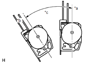
(a) Before installing the rear seat 3 point type outer belt assembly, check the ELR function. Text in Illustration
(1) When the inclination of the retractor is 15° or less, check that the belt can be pulled from the retractor. When the inclination of the retractor is over 45°, check that the belt locks. NOTICE: Do not disassemble the retractor. If operation is not as specified, replace the rear seat 3 point type outer belt assembly. |
|
|
(b) Engage the 2 guides to temporarily install the rear seat 3 point type outer belt assembly with the 2 bolts. |
|
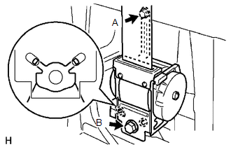
(c) Tighten bolt A, and then tighten bolt B.
Torque:
12.5 N·m {127 kgf·cm, 9 ft·lbf}
(for bolt A)
42 N·m {428 kgf·cm, 31 ft·lbf}
(for bolt B)
(d) Tighten the bolt to connect the shoulder anchor.
Torque:
42 N·m {428 kgf·cm, 31 ft·lbf}
(e) Check that the shoulder anchor rotates smoothly.
|
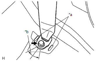
(f) Connect the floor anchor with the bolt. Text in Illustration
Torque: 42 N·m {428 kgf·cm, 31 ft·lbf} NOTICE:
|
|
(g) Check the ELR lock.
NOTICE:
The check should be performed with the rear seat 3 point type outer belt assembly installed.
(1) With the belt installed, check that the belt locks when it is pulled out quickly.
If the operation is not as specified, replace the rear seat 3 point type outer belt assembly.
(h) Remove the bolt to disconnect the floor anchor.
2. INSTALL QUARTER INSIDE TRIM BOARD
.gif)
3. CONNECT REAR SEAT 3 POINT TYPE OUTER BELT ASSEMBLY
4. INSTALL QUARTER TRIM LOWER PANEL
5. INSTALL LUGGAGE COMPARTMENT SIDE TRAY
6. CONNECT REAR DOOR OPENING TRIM WEATHERSTRIP
7. INSTALL REAR DOOR SCUFF PLATE
8. INSTALL REAR SEATBACK HINGE SUB-ASSEMBLY
9. INSTALL REAR SEATBACK ASSEMBLY
10. INSTALL REAR SEATBACK HINGE COVER
 Components
COMPONENTS
ILLUSTRATION
ILLUSTRATION
...
 Removal
REMOVAL
PROCEDURE
1. REMOVE REAR SEATBACK HINGE COVER
2. REMOVE REAR SEATBACK ASSEMBLY
3. REMOVE REAR SEATBACK HINGE SUB-ASSEMBLY
4. REMOVE REAR DOOR SCUFF PLATE
5. DISCONNECT REAR ...
Other materials:
Removal
REMOVAL
PROCEDURE
1. REMOVE FRONT WHEEL
2. DRAIN DIFFERENTIAL OIL
3. SEPARATE FRONT SPEED SENSOR
(a) Remove the bolt and separate the front speed sensor.
(b) Disengage the 2 clamps.
(c) Remove the bolt and separate the speed sensor wire harness from the steering
knuckle.
4. SEPARATE TIE ...
Precaution
PRECAUTION
1. PRECAUTION
NOTICE:
When disconnecting the cable from the negative (-) battery terminal,
initialize the following systems after the cable is reconnected (See page
).
Perform the Reset Memory procedures (A/T initialization) after replacing
the automatic transmi ...
Freeze Frame Data
FREEZE FRAME DATA
CHECK FREEZE FRAME DATA
HINT:
The ECU records vehicle and driving condition information as freeze frame data
the moment a DTC is stored.
(a) Connect the Techstream to the DLC3.
(b) Turn the ignition switch to ON.
(c) Turn the Techstream on.
(d) Enter the following menus: P ...
