Toyota Tacoma (2015-2018) Service Manual: Reassembly
REASSEMBLY
CAUTION / NOTICE / HINT
NOTICE:
When installing, coat the parts indicated by the arrows with power steering fluid
(See page .gif) ).
).
PROCEDURE
1. INSTALL VANE PUMP HOUSING OIL SEAL
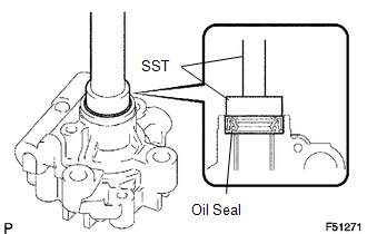
(a) Coat a new vane pump housing oil seal lip with power steering fluid.
(b) Using SST and a press, install a new oil seal.
SST: 09950-60010
09951-00280
SST: 09950-70010
09951-07100
NOTICE:
Make sure that the oil seal is installed facing in the correct direction.
2. INSTALL PULLEY SHAFT SUB-ASSEMBLY
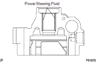
(a) Coat the bushing inner surface of the vane pump housing front with power steering fluid.
(b) Gradually insert the vane pump shaft.
NOTICE:
Do not damage the vane pump housing oil seal lip in the vane pump housing front.
3. INSTALL VANE PUMP SIDE PLATE FRONT
.png)
(a) Coat a new O-ring with power steering fluid and install it onto the vane pump housing front.
|
(b) Coat a new O-ring with power steering fluid and install it onto the side plate. |
|
.png)
|
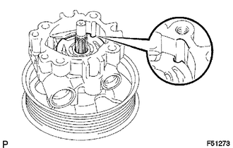
(c) Align the dent of the side plate with that of the vane pump housing front and install the side plate. NOTICE: Make sure that the side plate is installed facing the correct direction. |
|
4. INSTALL VANE PUMP CAM RING
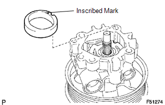
(a) Align the dent of the cam ring with that of the side plate and install the cam ring with the inscribed mark facing outward.
5. INSTALL VANE PUMP ROTOR
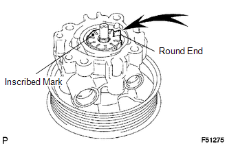
(a) Install the vane pump rotor with the inscribed mark facing outward.
(b) Coat the 10 vane plates with power steering fluid.
(c) Install the vane plates with the round ends facing outward.
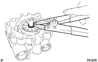
|
(d) Using a snap ring expander, install a new snap ring onto the pulley shaft. |
|
6. INSTALL VANE PUMP HOUSING REAR
(a) Coat a new O-ring with power steering fluid and install it onto the vane pump housing rear.
(b) Align the straight pin of the vane pump housing rear with the dents of the cam ring, side plate and vane pump housing front, and install the vane pump housing rear with the 4 bolts.
Torque:
22 N·m {224 kgf·cm, 16 ft·lbf}
7. INSPECT PRELOAD
(a) Check that the pump rotates smoothly without making any abnormal noises.
(b) Provisionally install the service bolt.
Recommended service bolt:
Thread diameter
10 mm (0.3937 in.)
Thread pitch
1.25 mm (0.0492 in.)
Bolt length
50 mm (1.9685 in.)
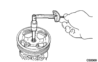
(c) Using a torque wrench, check the pump rotating torque.
Torque:
0.27 N·m {2.8 kgf·cm, 2.4 in·lbf}
or less
8. INSTALL POWER STEERING OIL PRESSURE SWITCH
(a) Coat the O-ring with power steering fluid and install it onto the power steering oil pressure switch.
(b) Install the power steering oil pressure switch onto the vane pump assembly.
Torque:
21 N·m {214 kgf·cm, 15 ft·lbf}
9. INSTALL FLOW CONTROL VALVE
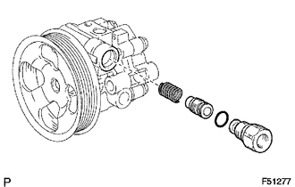
(a) Coat the compression spring and flow control valve with power steering fluid.
(b) Install the compression spring and flow control valve.
(c) Coat a new O-ring with power steering fluid and install it onto the pressure port union.
(d) Install the pressure port union.
Torque:
69 N·m {704 kgf·cm, 51 ft·lbf}
10. INSTALL VANE PUMP OIL RESERVOIR SUB-ASSEMBLY
(a) Coat a new O-ring with power steering fluid, and install it onto the vane pump oil reservoir.
(b) Install the vane pump oil reservoir with the 3 bolts.
Torque:
9.0 N·m {92 kgf·cm, 80 in·lbf}
 Installation
INSTALLATION
PROCEDURE
1. INSTALL VANE PUMP
(a) Install the vane pump assembly with the 2 bolts.
Torque:
21 N·m {214 kgf·cm, 15 ft·lbf}
(b) Connect the oil pressure switch conne ...
 Steering Column
...
Other materials:
Check Bus 3 Line for Short to +B
DESCRIPTION
There may be a short circuit between one of the CAN bus lines and +B when no
resistance exists between terminal 6 (CA3H) of the central gateway ECU (network
gateway ECU) and terminal 16 (BAT) of the DLC3, or terminal 21 (CA3L) of the central
gateway ECU (network gateway ECU) and t ...
Inspection
INSPECTION
PROCEDURE
1. INSPECT COOLER (ROOM TEMPERATURE. SENSOR) THERMISTOR
(a) Check the resistance.
(1) Measure the resistance according to the value(s) in the table below.
Text in Illustration
*a
Component without harness connected
(coo ...
Diagnostic Trouble Code Chart
DIAGNOSTIC TROUBLE CODE CHART
Air Conditioning System
DTC Code
Detection Item
Memory
See page
B1411/11
Room Temperature Sensor Circuit
Memorized
(4 seconds or more)
B1412/12
...
