Toyota Tacoma (2015-2018) Service Manual: Short in Driver Side Knee Airbag Squib Circuit (B1860/64-B1863/64)
DESCRIPTION
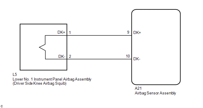
The driver side knee airbag squib circuit consists of the airbag sensor assembly and lower No. 1 instrument panel airbag assembly.
The airbag sensor assembly uses this circuit to deploy the airbag when deployment conditions are met.
These DTCs are stored when a malfunction is detected in the driver side knee airbag squib circuit.
|
DTC No. |
DTC Detection Condition |
Trouble Area |
|---|---|---|
|
B1860/64 |
|
|
|
B1861/64 |
|
|
|
B1862/64 |
|
|
|
B1863/64 |
|
WIRING DIAGRAM
CAUTION / NOTICE / HINT
NOTICE:
After turning the ignition switch off, waiting time may be required before disconnecting
the cable from the negative (-) battery terminal. Therefore, make sure to read the
disconnecting the cable from the negative (-) battery terminal notices before proceeding
with work (See page .gif) ).
).
HINT:
- Perform the simulation method by selecting check mode (Signal Check)
using the Techstream (See page ).
- After selecting check mode (Signal Check), perform the simulation method
by wiggling each connector of the airbag system or driving the vehicle on
a city road or rough road (See page
).
PROCEDURE
|
1. |
CHECK CONNECTORS |
|
(a) Turn the ignition switch off. |
|
(b) Disconnect the cable from the negative (-) battery terminal.
CAUTION:
Wait at least 90 seconds after disconnecting the cable from the negative (-) battery terminal to disable the SRS system.
(c) Check that the connectors are properly connected to the lower No. 1 instrument panel airbag assembly and airbag sensor assembly.
OK:
The connectors are properly connected.
HINT:
If the connectors are not connected securely, reconnect the connectors and proceed to the next inspection.
(d) Disconnect the connectors from the lower No. 1 instrument panel airbag assembly and airbag sensor assembly.
(e) Check that the terminals of the connectors are not damaged.
OK:
The terminals are not deformed or damaged.
(f) Check that the instrument panel wire connector (on the lower No. 1 instrument panel airbag assembly side) is not damaged.
OK:
The lock button is not disengaged, and the claw of the lock is not deformed or damaged.
(g) Check that the short spring for the instrument panel wire with the activation prevention mechanism are not deformed or damaged.
OK:
The short spring is not deformed or damaged.
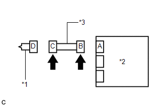
Text in Illustration|
*1 |
Driver Side Knee Airbag Squib |
|
*2 |
Airbag Sensor Assembly |
|
*3 |
Instrument Panel Wire |
| NG | .gif) |
REPLACE INSTRUMENT PANEL WIRE |
|
.gif)
|
2. |
CHECK LOWER NO. 1 INSTRUMENT PANEL AIRBAG ASSEMBLY (DRIVER SIDE KNEE AIRBAG SQUIB) |
|
(a) Connect the connector to the airbag sensor assembly. |
|
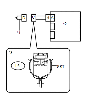
(b) Connect SST (resistance 2.1 Ω) to connector C.
CAUTION:
Never connect the tester to the lower No. 1 instrument panel airbag assembly (driver side knee airbag squib) for measurement, as this may lead to a serious injury due to airbag deployment.
NOTICE:
- Do not forcibly insert SST into the terminals of the connector when connecting it.
- Insert SST straight into the terminals of the connector.
SST: 09843-18061
(c) Connect the cable to the negative (-) battery terminal.
(d) Clear the DTCs stored in memory (See page
).
(e) Turn the ignition switch off.
(f) Turn the ignition switch to ON, and wait for at least 60 seconds.
(g) Check for DTCs (See page ).
OK:
DTC B1860/64, B1861/64, B1862/64 or B1863/64 is not output.
HINT:
Codes other than DTCs B1860/64, B1861/64, B1862/64 and B1863/64 may be output at this time, but they are not related to this check.
(h) Turn the ignition switch off.
(i) Disconnect the cable from the negative (-) battery terminal.
CAUTION:
Wait at least 90 seconds after disconnecting the cable from the negative (-) battery terminal to disable the SRS system.
(j) Disconnect SST from connector C.
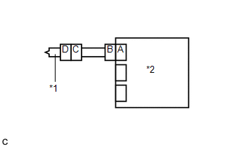
Text in Illustration|
*1 |
Driver Side Knee Airbag Squib |
|
*2 |
Airbag Sensor Assembly |
|
*a |
Front view of wire harness connector (to Lower No. 1 Instrument Panel Airbag Assembly) |
| OK | |
REPLACE LOWER NO. 1 INSTRUMENT PANEL AIRBAG ASSEMBLY |
|
|
3. |
CHECK INSTRUMENT PANEL WIRE |
|
(a) Disconnect the instrument panel wire from the airbag sensor assembly. |
|
(b) Check for a short to B+ in the circuit.
(1) Connect the cable to the negative (-) battery terminal.
(2) Turn the ignition switch to ON.
(3) Measure the voltage according to the value(s) in the table below.
Standard Voltage:
|
Tester Connection |
Switch Condition |
Specified Condition |
|---|---|---|
|
L5-1 (DK+) - Body ground |
Ignition switch ON |
Below 1 V |
|
L5-2 (DK-) - Body ground |
Ignition switch ON |
Below 1 V |
(4) Turn the ignition switch off.
(5) Disconnect the cable from the negative (-) battery terminal.
CAUTION:
Wait at least 90 seconds after disconnecting the cable from the negative (-) battery terminal to disable the SRS system.
(c) Check for an open in the circuit.
(1) Measure the resistance according to the value(s) in the table below.
Standard Resistance:
|
Tester Connection |
Condition |
Specified Condition |
|---|---|---|
|
L5-1 (DK+) - L5-2 (DK-) |
Always |
Below 1 Ω |
(d) Check for a short to ground in the circuit.
(1) Measure the resistance according to the value(s) in the table below.
Standard Resistance:
|
Tester Connection |
Condition |
Specified Condition |
|---|---|---|
|
L5-1 (DK+) - Body ground |
Always |
1 MΩ or higher |
|
L5-2 (DK-) - Body ground |
Always |
1 MΩ or higher |
(e) Check for a short in the circuit.
(1) Release the activation prevention mechanism built into connector B (See page
).
(2) Measure the resistance according to the value(s) in the table below.
Standard Resistance:
|
Tester Connection |
Condition |
Specified Condition |
|---|---|---|
|
L5-1 (DK+) - L5-2 (DK-) |
Always |
1 MΩ or higher |
(3) Restore the released activation prevention mechanism of connector B to the original condition.
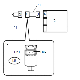
Text in Illustration|
*1 |
Driver Side Knee Airbag Squib |
|
*2 |
Airbag Sensor Assembly |
|
*3 |
Instrument Panel Wire |
|
*a |
Front view of wire harness connector (to Lower No. 1 Instrument Panel Airbag Assembly) |
| NG | |
REPLACE INSTRUMENT PANEL WIRE |
|
|
4. |
CHECK DTC |
|
(a) Connect the connectors to the lower No. 1 instrument panel airbag assembly and airbag sensor assembly. |
|
(b) Connect the cable to the negative (-) battery terminal.
(c) Turn the ignition switch to ON, and wait for at least 60 seconds.
(d) Clear the DTCs stored in memory (See page
).
(e) Turn the ignition switch off.
(f) Turn the ignition switch to ON, and wait for at least 60 seconds.
(g) Check for DTCs (See page ).
OK:
DTC B1860/64, B1861/64, B1862/64 or B1863/64 is not output.
HINT:
Codes other than DTCs B1860/64, B1861/64, B1862/64 and B1863/64 may be output at this time, but they are not related to this check.
Text in Illustration|
*1 |
Lower No. 1 Instrument Panel Airbag Assembly |
|
*2 |
Airbag Sensor Assembly |
| OK | |
USE SIMULATION METHOD TO CHECK |
| NG | |
REPLACE AIRBAG SENSOR ASSEMBLY |
 Short in Curtain Shield Squib LH Circuit (B1835/58-B1838/58)
DESCRIPTION
The driver side curtain shield squib circuit consists of the airbag sensor assembly
and the curtain shield airbag assembly LH.
The circuit signals the SRS to deploy when airbag deploym ...
 Short in Front Passenger Side Knee Airbag Squib Circuit (B1865/65-B1868/65)
DESCRIPTION
The passenger side knee airbag squib circuit consists of the airbag sensor assembly
and lower No. 2 instrument panel airbag assembly.
The airbag sensor assembly uses this circuit to de ...
Other materials:
Installation
INSTALLATION
PROCEDURE
1. INSTALL OIL COOLER ASSEMBLY (w/ Air Cooled Transmission Oil Cooler)
(a) Install the 2 oil cooler brackets to the oil cooler assembly with the 2 bolts.
Torque:
5.5 N·m {56 kgf·cm, 49 in·lbf}
(b) Install the oil cooler assembly to the vehicle body with th ...
Radar Cruise Control Presence Determination Malfunction (Engine / HV) (C1A52)
DESCRIPTION
DTC C1A52 is stored when the ECM cannot recognize the millimeter wave radar sensor
assembly.
DTC No.
Detection Item
DTC Detection Condition
Trouble Area
C1A52
Radar Cruise Control Presence Determination Malfuncti ...
Problem Symptoms Table
PROBLEM SYMPTOMS TABLE
HINT:
Use the table below to help determine the cause of problem symptoms.
If multiple suspected areas are listed, the potential causes of the symptoms
are listed in order of probability in the "Suspected Area" column of the
table. Check each sy ...
