Toyota Tacoma (2015-2018) Service Manual: Removal
REMOVAL
PROCEDURE
1. PRECAUTION
CAUTION:
Be sure to read Precaution thoroughly before servicing (See page
.gif) ).
).
NOTICE:
After turning the ignition switch off, waiting time may be required before disconnecting the cable from the negative (-) battery terminal. Therefore, make sure to read the disconnecting the cable from the negative (-) battery terminal notices before proceeding with work.
Click here
2. DISCONNECT CABLE FROM NEGATIVE BATTERY TERMINAL
CAUTION:
Wait at least 90 seconds after disconnecting the cable from the negative (-) battery terminal to prevent airbag and seat belt pretensioner activation.
NOTICE:
When disconnecting the cable, some systems need to be initialized after the cable is reconnected.
Click here
3. REMOVE INSTRUMENT SIDE PANEL RH
4. REMOVE GLOVE COMPARTMENT PLATE
5. REMOVE LOWER NO. 2 INSTRUMENT PANEL AIRBAG ASSEMBLY
|
(a) Remove the 3 bolts. Text in Illustration
|
|
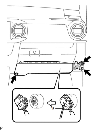
(b) Using a screwdriver with its tip wrapped in protective tape, release the airbag connector lock.
(c) Disconnect the airbag connector to remove the lower No. 2 instrument panel airbag assembly.
NOTICE:
When handling the airbag connector, take care not to damage the airbag wire harness.
 On-vehicle Inspection
ON-VEHICLE INSPECTION
PROCEDURE
1. INSPECT LOWER NO. 2 INSTRUMENT PANEL AIRBAG ASSEMBLY (for Vehicle not Involved
in Collision)
(a) Perform a diagnostic system check (See page
).
...
 Disposal
DISPOSAL
CAUTION / NOTICE / HINT
CAUTION:
Before performing pre-disposal deployment of any SRS part, review and closely
follow all applicable environmental and hazardous material regulations. Pre ...
Other materials:
Installation
INSTALLATION
CAUTION / NOTICE / HINT
CAUTION:
Wear protective gloves. Sharp areas on the parts may injure your hands.
HINT:
Use the same procedure for both the RH and LH sides.
The procedure described below is for the LH side.
PROCEDURE
1. INSTALL FRONT SEAT AIRBAG ASSEMBLY ...
Auto Down Operation does not Fully Open Power Window (Catch Protection Function
is Activated)
DESCRIPTION
If a front door glass or the power window regulator motor assembly (for driver
door) or power window regulator motor assembly (front passenger door) does not operate
smoothly, the catch protection function may be triggered automatically, resulting
in the auto down operation being ...
Installation
INSTALLATION
CAUTION / NOTICE / HINT
HINT:
Use the same procedures for both the LH and RH sides.
The procedure described below is for the LH side.
PROCEDURE
1. INSTALL OUTER REAR VIEW MIRROR ASSEMBLY
(a) Engage the claw to install the outer rear view mirror assembly.
(b) Ins ...
