Toyota Tacoma (2015-2018) Service Manual: Disposal
DISPOSAL
CAUTION / NOTICE / HINT
CAUTION:
Before performing pre-disposal deployment of any SRS part, review and closely follow all applicable environmental and hazardous material regulations. Predisposal deployment may be considered hazardous material treatment.
PROCEDURE
1. PRECAUTION
CAUTION:
- An airbag or pretensioner may be activated by static electricity. To prevent this, be sure to touch a metal surface with your bare hands to discharge static electricity before performing this procedure.
- Never dispose of a lower No. 2 instrument panel airbag assembly with an undeployed airbag.
- The airbag produces an exploding sound when it is deployed, so perform the operation outdoors and where it will not create a nuisance to nearby residents.
- When deploying the airbag, always use the specified SST (SRS Airbag Deployment Tool). Perform the operation in a place away from electrical noise.
- When deploying the airbag, perform the operation at least 10 m (32.8 ft.) away from the lower No. 2 instrument panel airbag assembly.
- The lower No. 2 instrument panel airbag assembly becomes extremely hot when the airbag is deployed, so do not touch it for at least 30 minutes after deployment.
- Use gloves and safety glasses when handling a lower No. 2 instrument panel airbag assembly with a deployed airbag.
- Do not apply water etc. to a lower No. 2 instrument panel airbag assembly with a deployed airbag.
- Always wash your hands with water after completing the operation.
HINT:
When scrapping a vehicle equipped with the SRS or disposing of the lower No. 2 instrument panel airbag assembly, be sure to deploy the airbag first in accordance with the procedure described below. If any abnormality occurs with the airbag deployment, contact the SERVICE DEPT. of TOYOTA MOTOR SALES, U.S.A., INC.
2. DISPOSE OF LOWER NO. 2 INSTRUMENT PANEL AIRBAG ASSEMBLY (When Installed in Vehicle)
NOTICE:
- When disposing of the lower No. 2 instrument panel airbag assembly, never use the customer's vehicle to deploy the airbag.
- Be sure to observe the following procedure when deploying the airbag.
HINT:
Prepare a battery as the power source to deploy the airbag.
|
(a) Check the function of SST (See page
|
|
.png)
(b) Read the precaution (See page .gif) ).
).
(c) Disconnect the cable from the negative (-) battery terminal.
CAUTION:
Wait at least 90 seconds after disconnecting the cable from the negative (-) battery terminal to disable the SRS system.
(d) Remove the lower No. 2 instrument panel airbag assembly (See page
).
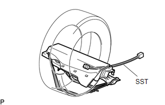
(e) Install SST.
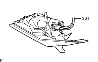
(1) Connect SST connector to the lower No. 2 instrument panel airbag assembly.
SST: 09082-00700
SST: 09082-00802
09082-10801
09082-20801
NOTICE:
To avoid damaging SST connector and wire harness, do not lock the secondary lock of the twin lock.
(2) Install the lower No. 2 instrument panel airbag assembly (See page
).
NOTICE:
Take care not to damage SST wire harness.
|
(3) Move SST at least 10 m (32.8 ft.) away from the vehicle front side window. Text in Illustration
|
|
(4) While maintaining sufficient clearance for the SST wire harness in the front side window, close all doors and windows of the vehicle.
NOTICE:
Take care not to damage the SST wire harness.
(5) Connect the red clip of SST to the positive (+) battery terminal and the black clip of SST to the negative (-) battery terminal.
(f) Deploy the airbag.
(1) Check that no one is inside the vehicle or within a 10 m (32.8 ft.) radius of the vehicle.
(2) Press SST activation switch to deploy the airbag.
CAUTION:
- Before deployment, make sure that no one is near the vehicle.
- The lower No. 2 instrument panel airbag assembly becomes extremely hot when the airbag is deployed, so do not touch it for at least 30 minutes after deployment.
- Use gloves and safety glasses when handling a lower No. 2 instrument panel airbag assembly with a deployed airbag.
- Do not apply water etc. to a lower No. 2 instrument panel airbag assembly with a deployed airbag.
- Always wash your hands with water after completing the operation.
HINT:
The airbag is deployed as the LED of the SST activation switch comes on.
3. DISPOSE OF LOWER NO. 2 INSTRUMENT PANEL AIRBAG ASSEMBLY (When Not Installed in Vehicle)
NOTICE:
Be sure to follow the procedure detailed below when deploying the airbag.
HINT:
Prepare a battery as the power source to deploy the airbag.
|
(a) Check the function of SST (See page
|
|
(b) Remove the lower No. 2 instrument panel airbag assembly (See page
).
CAUTION:
- When removing the lower No. 2 instrument panel airbag assembly, wait at least 90 seconds after the ignition switch is turned off and the cable is disconnected from the negative (-) battery terminal before starting work.
- When storing the lower No. 2 instrument panel airbag assembly, keep the airbag deployment side facing upward.
(c) Using a service-purpose wire harness for the vehicle, tie down the lower No. 2 instrument panel airbag assembly to a tire.
 Text in Illustration
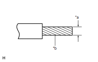
|
*a |
Wire Diameter |
|
*b |
Stripped Wire |
Wire:
Cross-sectional area of stripped wire
1.25 mm2 or more (0.0019 in.2 or more)
CAUTION:
If the wire harness is too thin or an alternative object is used to tie down the lower No. 2 instrument panel airbag assembly, it may be snapped by the shock when the airbag is deployed. Always use a wire harness for vehicle use with a cross-sectional area of at least 1.25 mm2 (0.00192 in.2).
HINT:
To calculate the cross-sectional area of the stripped wire section: Area = 3.14 x (Diameter)2 / 4
(1) Position the lower No. 2 instrument panel airbag assembly inside a tire with the airbag deployment side facing inside.
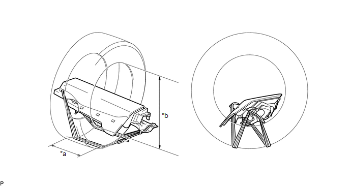 Text in Illustration
|
*a |
Width |
*b |
Inner Diameter |
Tire size:
Must exceed the following dimensions
Width
185 mm (7.28 in.)
Inner diameter
360 mm (14.2 in.)
(2) Tie the lower No. 2 instrument panel airbag assembly to the tire with several wire harnesses.
CAUTION:
- Make sure that the wire harnesses are tight. If there is slack in the wire harnesses, the lower No. 2 instrument panel airbag assembly may become loose due to the shock when the airbag is deployed.
- Always tie down the lower No. 2 instrument panel airbag assembly with the airbag deployment side facing inside the tire.
NOTICE:
As the tire may be damaged by the airbag deployment, use a tire that you are planning to throw away.
|
(d) Connect SST connector to the lower No. 2 instrument panel airbag assembly. SST: 09082-00802 09082-10801 09082-20801 |
|
(e) Place tires.
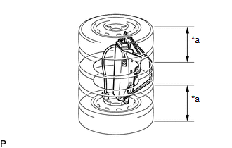
(1) Place at least 2 tires under the tire which the lower No. 2 instrument panel airbag assembly is tied to.
Text in Illustration|
*a |
Tire (2 or more) |
(2) Place at least 2 tires over the tire which the lower No. 2 instrument panel airbag assembly is tied to. The top tire should have a disc wheel installed.
NOTICE:
- Do not place SST connector under the tires because it could be damaged.
- As the disc wheel may be damaged by the airbag deployment, use a disc wheel that you are planning to throw away.
- As the tires may be damaged by the airbag deployment, use tires that you are planning to throw away.
|
(3) Tie the tires together with 2 wire harnesses. CAUTION: Make sure that the wire harnesses are tight. Looseness in the wire harnesses results in the tires coming free due to the shock when the airbag is deployed. |
|
.png)
|
(f) Connect SST connector. SST: 09082-00700 NOTICE: To avoid damaging SST connector and wire harness, do not lock the secondary lock of the twin lock. Also, secure some slack for SST wire harness inside the tires. |
|
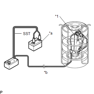
(g) Deploy the airbag.
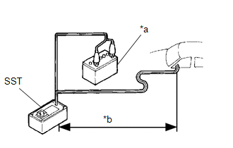
(1) Connect the red clip of SST to the positive (+) battery terminal and the black clip of SST to the negative (-) battery terminal.
Text in Illustration|
*1 |
Lower No. 2 Instrument Panel Airbag Assembly |
|
*a |
Battery |
|
*b |
10 m (32.8 ft.) or more |
(2) Check that no one is within a 10 m (32.8 ft.) radius of the tire which the lower No. 2 instrument panel airbag assembly is tied to.
(3) Press the SST activation switch and deploy the airbag.
CAUTION:
Before deployment, make sure that no one is near the airbag.
HINT:
The airbag is deployed as the LED of the SST activation switch comes on.
(h) Dispose of the lower No. 2 instrument panel airbag assembly.
CAUTION:
- The lower No. 2 instrument panel airbag assembly becomes extremely hot when the airbag is deployed, so do not touch it for at least 30 minutes after deployment.
- Use gloves and safety glasses when handling a lower No. 2 instrument panel airbag assembly with a deployed airbag.
- Do not apply water to a lower No. 2 instrument panel airbag assembly with a deployed airbag.
- Always wash your hands with water after completing the operation.
(1) Remove the lower No. 2 instrument panel airbag assembly from the tire.
(2) Dispose of lower No. 2 instrument panel airbag assembly, according to local regulations.
 Removal
REMOVAL
PROCEDURE
1. PRECAUTION
CAUTION:
Be sure to read Precaution thoroughly before servicing (See page
).
NOTICE:
After turning the ignition switch off, waiting time may be required before ...

Other materials:
Terminals Of Ecu
TERMINALS OF ECU
1. CHECK ENGINE SWITCH
(a) Measure the resistance and voltage according to the value(s) in the table
below.
Terminal No. (Symbol)
Input/Output
Wiring Color
Terminal Description
Condition
Specified Condition
...
Data List / Active Test
DATA LIST / ACTIVE TEST
1. READ DATA LIST
HINT:
Using the Techstream to read the Data List allows the values or states of switches,
sensors, actuators and other items to be read without removing any parts. This non-intrusive
inspection can be very useful because intermittent conditions or sig ...
Vehicle data recordings
Your Toyota is equipped with several sophisticated computers that will record
certain data, such as: ŌĆó Engine speed
ŌĆó Accelerator status
ŌĆó Brake status
ŌĆó Vehicle speed
ŌĆó Shift position (except manual transmission)
The recorded data varies according to the vehicle grade level and opt ...
