Toyota Tacoma (2015-2018) Service Manual: Removal
REMOVAL
PROCEDURE
1. REMOVE TRANSMISSION INSULATOR RH (for 2GR-FKS)
.gif)
2. REMOVE TRANSMISSION INSULATOR RH (for 2TR-FE)
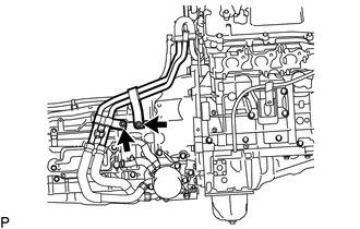
3. SEPARATE WATER BY-PASS PIPE (for 2GR-FKS)
|
(a) Remove the 2 bolts to separate the water by-pass pipe from the automatic transmission assembly. |
|
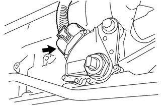
4. REMOVE PARK/NEUTRAL POSITION SWITCH
|
(a) Disconnect the park/neutral position switch connector. |
|
|
(b) Using a screwdriver, pry out the lock washer. |
|
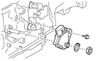
(c) Remove the nut and lock washer.
(d) Remove the bolt and park/neutral position switch from the automatic transmission assembly.
HINT:
Make sure that the manual valve lever shaft has not been rotated prior to installing the park/neutral position switch as the detent spring may become detached from the manual valve lever shaft.
 On-vehicle Inspection
ON-VEHICLE INSPECTION
PROCEDURE
1. INSPECT PARK/NEUTRAL POSITION SWITCH
(a) Apply the parking brake.
(b) Turn the ignition switch to ON.
(c) Depress the brake pedal and move the shift lever to an ...
 Adjustment
ADJUSTMENT
PROCEDURE
1. ADJUST PARK/NEUTRAL POSITION SWITCH
(a) While pushing the shift lock release button, move the shift lever to N.
(b) Remove the bolt of the park/neutral position switch.
(c ...
Other materials:
Removal
REMOVAL
PROCEDURE
1. REMOVE FRONT DOOR SCUFF PLATE LH
for Double Cab:
Click here
for Access Cab:
Click here
2. REMOVE COWL SIDE TRIM BOARD LH
Click here
3. REMOVE INSTRUMENT CLUSTER CENTER FINISH PANEL SUB-ASSEMBLY
Click here
4. REMOVE INSTRUMENT CLUSTER FINISH PANEL ASSEMBLY
Cli ...
Hood
Release the lock from the inside of the vehicle to open the hood.
Pull the hood release lever.
The hood will pop up slightly.
Pull up the hood catch lever and lift the hood.
Hold the hood open by inserting the supporting rod into the slot.
CAUTION
■Pre-driving check
Check that the ...
Inspection
INSPECTION
PROCEDURE
1. INSPECT FUEL PUMP ASSEMBLY
(a) Measure the resistance according to the value(s) in the table below.
Standard Resistance:
Tester Connection
Condition
Specified Condition
1 - 2
20°C (68°F)
0.45 to 0 ...
