Toyota Tacoma (2015-2018) Service Manual: On-vehicle Inspection
ON-VEHICLE INSPECTION
PROCEDURE
1. INSPECT LOWER NO. 2 INSTRUMENT PANEL AIRBAG ASSEMBLY (for Vehicle not Involved in Collision)
|
(a) Perform a diagnostic system check (See page
|
|
.gif) ).
).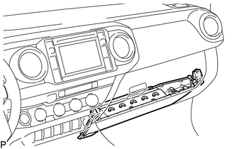
(b) With the lower No. 2 instrument panel airbag assembly installed on the vehicle, perform a visual check. If there are any defects as mentioned below, replace the lower No. 2 instrument panel airbag assembly with a new one:
Cuts, minute cracks or marked discoloration on the lower No. 2 instrument panel airbag assembly.
2. INSPECT LOWER NO. 2 INSTRUMENT PANEL AIRBAG ASSEMBLY (for Vehicle Involved in Collision and Airbag has not Deployed)
|
(a) Perform a diagnostic system check (See page
|
|
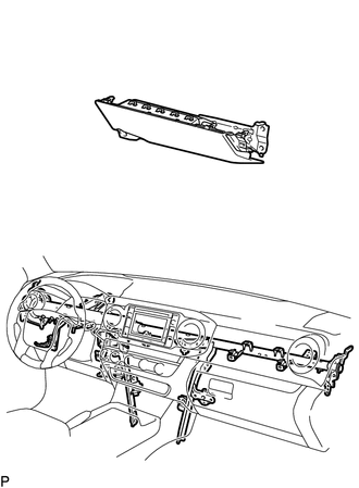
(b) With the lower No. 2 instrument panel airbag assembly removed from the vehicle, perform a visual check. If there are any defects as mentioned below, replace the lower No. 2 instrument panel airbag assembly with a new one:
- Cuts, minute cracks or marked discoloration on the lower No. 2 instrument panel airbag assembly.
- Cracks or other damage to the connector.
- Deformation or cracks on the instrument panel reinforcement.
CAUTION:
For removal and installation procedures of the lower No. 2 instrument panel airbag assembly, be sure to follow the correct procedure.
 Installation
INSTALLATION
PROCEDURE
1. INSTALL LOWER NO. 2 INSTRUMENT PANEL AIRBAG ASSEMBLY
(a) Connect the airbag connector.
NOTICE:
When handling the airbag connector, take care not to damage ...
 Removal
REMOVAL
PROCEDURE
1. PRECAUTION
CAUTION:
Be sure to read Precaution thoroughly before servicing (See page
).
NOTICE:
After turning the ignition switch off, waiting time may be required before ...
Other materials:
Check Mode Procedure
CHECK MODE PROCEDURE
1. DESCRIPTION
(a) Check mode has a higher sensitivity to malfunctions and can detect malfunctions
that normal mode cannot detect. Check mode can also detect all the malfunctions
that normal mode can detect. In check mode, DTCs are detected with 1 trip detection
logic.
...
On-vehicle Inspection
ON-VEHICLE INSPECTION
PROCEDURE
1. INSPECT ENGINE COOLANT
(See page )
2. INSPECT ENGINE OIL
(See page )
3. INSPECT BATTERY
(See page )
4. INSPECT SPARK PLUG
(See page )
5. INSPECT AIR CLEANER FILTER ELEMENT SUB-ASSEMBLY
(a) Remove the air cleaner filter element sub-assembly.
(b) Visu ...
High Power Supply Voltage Malfunction (C1417)
DESCRIPTION
If a malfunction is detected in the power supply circuit, the skid control ECU
(brake actuator assembly) stores this DTC and the fail-safe function prohibits ABS
operation.
This DTC is stored when the +BS terminal voltage deviates from the DTC detection
condition due to a malfunc ...
