Toyota Tacoma (2015-2018) Service Manual: Removal
REMOVAL
PROCEDURE
1. REMOVE ROOF HEADLINING ASSEMBLY (for LED Type Stop Light)
- for Double Cab:
(See page
.gif) )
) - for Access Cab:
(See page
)
2. REMOVE CENTER STOP LIGHT ASSEMBLY (for Bulb Type Stop Light)
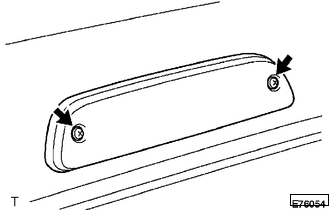
(a) Apply protective tape around the center stop light assembly.
.png) Text in Illustration
Text in Illustration
.png) |
Protective Tape |
|
(b) Remove the 2 screws and separate the center stop light assembly. |
|
|
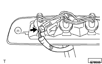
(c) Disconnect the connector to remove the center stop light assembly. |
|
|
(d) Turn the 3 center stop light sockets with the 3 center stop light bulbs in the direction indicated by the arrow shown in the illustration to remove them. |
|
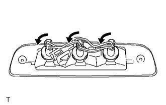
(e) To remove the 3 center stop light sockets and bulbs, turn them in the direction indicated by the arrow in the illustration.
3. REMOVE CENTER STOP LIGHT ASSEMBLY (for LED Type Stop Light)
|
(a) Remove the 2 nuts. |
|
.png)
(b) Apply protective tape around the center stop light assembly.
Text in Illustration
|
|
Protective Tape |
|
(c) Using a moulding remover D, disengage the 2 clips to separate the center stop light assembly. |
|
.png)
|
(d) Disconnect the connector to remove the center stop light assembly. |
|
.png)
 Inspection
INSPECTION
PROCEDURE
1. INSPECT CENTER STOP LIGHT ASSEMBLY (for LED Type Stop Light)
(a) Check the illuminates.
(1) Apply battery voltage to the connector and check the light illuminati ...
 Installation
INSTALLATION
PROCEDURE
1. INSTALL CENTER STOP LIGHT ASSEMBLY (for Bulb Type Stop Light)
(a) Install the 3 center stop light bulbs to the 3 center stop light sockets.
(b) Turn the 3 cent ...
Other materials:
Installation
INSTALLATION
PROCEDURE
1. INSTALL FRONT NO. 2 SPEAKER ASSEMBLY RH
(a) Connect the connector.
(b) Install the front No. 2 speaker assembly RH with the 2 bolts.
Torque:
8.4 N·m {86 kgf·cm, 74 in·lbf}
NOTICE:
Do not touch the cone part of the front No. 2 speaker assembly RH.
...
Rear Center Seat Outer Belt Assembly(for Double Cab)
Components
COMPONENTS
ILLUSTRATION
Removal
REMOVAL
PROCEDURE
1. REMOVE REAR SEATBACK HINGE COVER
2. REMOVE REAR SEATBACK BOARD SUB-ASSEMBLY
3. REMOVE SEAT BELT ANCHOR COVER CAP
4. REMOVE REAR SEAT SHOULDER BELT COVER
5. REMOVE CENTER SEATBACK PAD
(a) Remove th ...
Removal
REMOVAL
PROCEDURE
1. PLACE FRONT WHEELS FACING STRAIGHT AHEAD
2. REMOVE FRONT WHEELS
3. REMOVE FRONT UPPER FENDER APRON SEAL
Click here
4. REMOVE NO. 2 ENGINE UNDER COVER SUB-ASSEMBLY (w/ Off Road Package)
5. REMOVE NO. 1 ENGINE UNDER COVER SUB-ASSEMBLY
6. REMOVE FRONT DIFFERENTIAL CARRI ...
