Toyota Tacoma (2015-2018) Service Manual: Installation
INSTALLATION
PROCEDURE
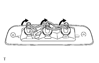
1. INSTALL CENTER STOP LIGHT ASSEMBLY (for Bulb Type Stop Light)
(a) Install the 3 center stop light bulbs to the 3 center stop light sockets.
|
(b) Turn the 3 center stop light sockets with 3 center stop light bulbs in the direction indicated by the arrow shown in the illustration to install them. |
|
(c) Connect the connector.
(d) Install the center stop light assembly with the 2 screws.
(e) Remove the protective tape.
2. INSTALL CENTER STOP LIGHT ASSEMBLY (for LED Type Stop Light)
(a) Connect the connector.
|
(b) Engage the 2 clips to install the center stop light assembly. |
|
.png)
(c) Install the 2 nuts.
Torque:
3.6 N·m {36 kgf·cm, 31 in·lbf}
(d) Remove the protective tape.
3. CONNECT ROOF HEADLINING ASSEMBLY (for LED Type Stop Light)
- for Double Cab:
(See page
.gif) )
) - for Access Cab:
(See page
)
 Removal
REMOVAL
PROCEDURE
1. REMOVE ROOF HEADLINING ASSEMBLY (for LED Type Stop Light)
for Double Cab:
(See page
)
for Access Cab:
(See page
)
2. REMOVE CENTER STOP ...
 Interior Illumination Light
Components
COMPONENTS
ILLUSTRATION
Removal
REMOVAL
PROCEDURE
1. REMOVE INSTRUMENT PANEL LOWER CENTER FINISH PANEL
(See page )
2. REMOVE NO. 1 INTERIOR ILLUMINATION LIGHT ASSEMBLY
...
Other materials:
Diagnostic Trouble Code Chart
DIAGNOSTIC TROUBLE CODE CHART
Charging System
DTC Code
Detection Item
Warning Indicate
Memory
SAE
See page
P161A87
Lost Communication with Alternator Missing Message
-
DTC stored
...
Dtc Check / Clear
DTC CHECK / CLEAR
HINT:
DTCs which are stored in the ECM can be displayed on the Techstream.
The Techstream can display pending DTCs and current DTCs. Some DTCs
are not stored unless a malfunction is detected in consecutive driving cycles.
When a malfunction is detected in o ...
Front Differential Oil Temperature Sensor Circuit High (P17C8)
DESCRIPTION
This DTC is output when a short to B+ or open circuit in the oil temperature
sensor is detected.
DTC No.
Detection Item
DTC Detection Condition
Trouble Area
P17C8
Front Differential Oil Temperature Sensor Circuit ...
