Toyota Tacoma (2015-2018) Service Manual: Trailer Socket
Components
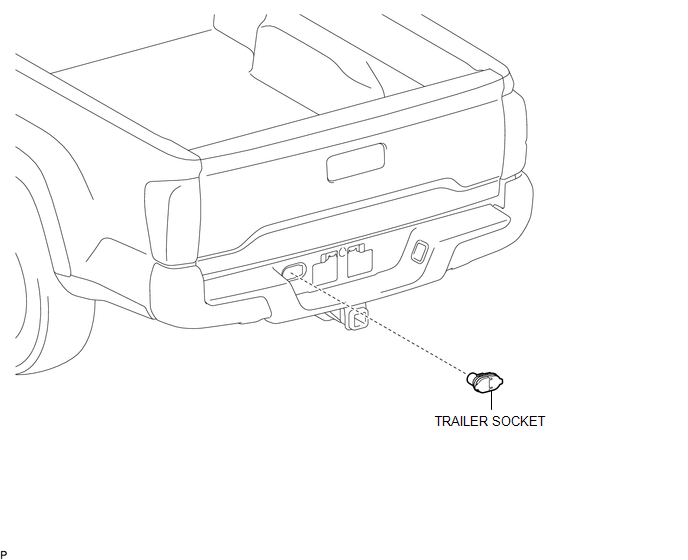
COMPONENTS
ILLUSTRATION
Removal
REMOVAL
PROCEDURE
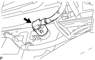
1. REMOVE TRAILER SOCKET
|
(a) Disconnect the connector. |
|
|
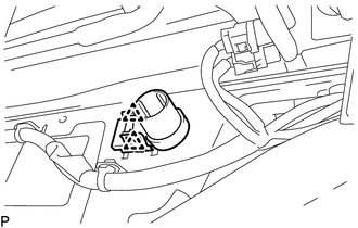
(b) Disengage the 2 clips to remove the trailer socket. |
|
Installation
INSTALLATION
PROCEDURE
1. INSTALL TRAILER SOCKET
(a) Engage the 2 clips to install the trailer socket.
(b) Connect the connector.
 Towing Tail Relay
Inspection
INSPECTION
PROCEDURE
1. INSPECT TOWING TAIL RELAY
(a) Check the resistance.
(1) Using an ohmmeter, measure the resistance between the terminals.
Standard:
Tester Conn ...
 Vanity Light
Components
COMPONENTS
ILLUSTRATION
Removal
REMOVAL
CAUTION / NOTICE / HINT
HINT:
Use the same procedures for the LH and RH side.
The procedures listed below are for the LH sid ...
Other materials:
Pressure Control Solenoid "G" Circuit Open (P280713)
DESCRIPTION
Changing from 1st to 6th is performed by the ECM turning shift solenoid valves
SL1, SL2, SL3 and SL4 on and off. If an open or short circuit occurs in any of the
shift solenoid valves, the ECM controls the remaining normal shift solenoid valves
to allow the vehicle to be operated ...
Air Conditioning Compressor Magnetic Clutch Circuit
DESCRIPTION
When the air conditioning amplifier assembly is turned on, a magnetic clutch
on signal is sent from the MGC terminal of the air conditioning amplifier assembly.
Then, the MG CLT relay turns on to operate the magnetic clutch assembly.
WIRING DIAGRAM
CAUTION / NOTICE / HINT
NO ...
Front Camera Module Incorrect Axial Gap (C1AA8,C1AA9)
DESCRIPTION
If the forward recognition camera detects that the forward recognition camera
axis has deviated, DTC C1AA8 is stored. Also, if Forward Recognition Camera Axis
Adjustment is not performed after installing the forward recognition camera, DTC
C1AA9 is stored.
DTC No.
...
