Toyota Tacoma (2015-2018) Service Manual: Vehicle Position Mark Deviates Greatly
CAUTION / NOTICE / HINT
NOTICE:
- If standard size tires are not installed, the vehicle position mark may deviate from the route even if the navigation system is operating normally.
- Make sure that standard size tires are installed to the vehicle before inspection.
PROCEDURE
|
1. |
CHECK CABIN |
(a) Check the cabin for any object that might interrupt radio reception on the instrument panel. If such an object exists, remove it and check if the vehicle position mark returns to the appropriate position.
HINT:
The GPS uses extremely faint radio waves originating from satellites. If the signal is interrupted by obstructions or other radio waves, the GPS may not be able to properly receive the signal.
OK:
After driving for a while, the vehicle position mark returns to the appropriate position.
| OK | .gif) |
NORMAL OPERATION |
|
.gif)
|
2. |
CHECK SURROUNDINGS |
(a) Check if the vehicle is in a location where GPS signal reception is poor. If the vehicle is in such a location, move the vehicle and check if the vehicle position mark returns to the appropriate position.
HINT:
The GPS uses 24 satellites in 6 orbits. At any point in time, 4 satellites should be able to pinpoint your vehicle. However, GPS signals may not reach the vehicle due to influence from the surroundings, vehicle direction and time. For examples, see the following illustration.
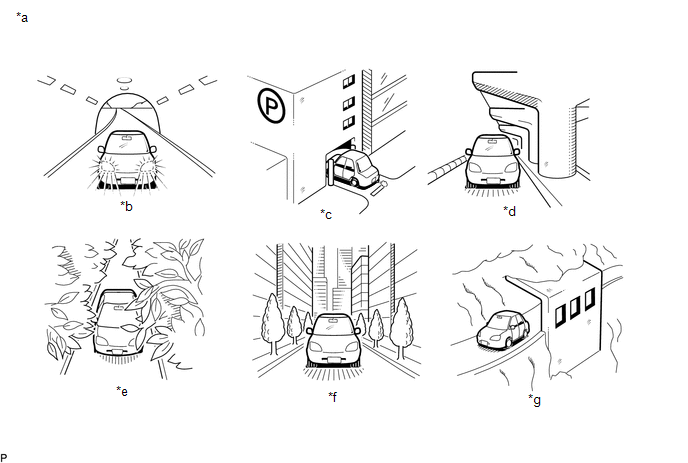 Text in Illustration
|
*a |
Example |
*b |
In a tunnel |
|
*c |
In a building |
*d |
Under an overpass |
|
*e |
On a forest or tree-lined path |
*f |
Between tall buildings |
|
*g |
Under a cliff or overhang |
- |
- |
OK:
After driving for a while, the vehicle position mark returns to the appropriate position.
| OK | |
SYSTEM RETURNS TO NORMAL |
|
|
3. |
CHECK GPS INFORMATION (OPERATION CHECK) |
|
(a) Enter the "System Sensor Check" screen. Refer to Check GPS & Vehicle
Sensors in Operation Check (See page |
|
.gif) ).
).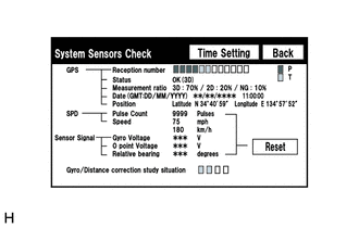
(b) Check how many of the following codes appear in the "Reception number" column.
HINT:
T or P appears.
OK:
At least 3 codes appear.
| OK | |
REPLACE NAVIGATION RECEIVER ASSEMBLY |
| NG | |
PROCEED TO NEXT SUSPECTED AREA SHOWN IN PROBLEM SYMPTOMS TABLE |
 Poor Sound Quality in All Modes (Low Volume)
PROCEDURE
1.
CHECK AUDIO SETTINGS
(a) Set "Treble", "Mid" and "Bass" to the initial values and check that sound
is normal.
OK:
Malf ...
 Cursor or Map Rotates when Vehicle Stopped
PROCEDURE
1.
CHECK CONDITION
(a) Check with the customer if the vehicle has been turned by a turntable.
OK:
Vehicle has not been turned by a turntab ...
Other materials:
Interior Light Circuit
DESCRIPTION
The illuminated entry system controls the interior lights.
WIRING DIAGRAM
CAUTION / NOTICE / HINT
NOTICE:
Inspect the fuses for circuits related to this system before performing
the following inspection procedure.
If the main body ECU (multiplex network body ECU) i ...
Open in One Side of Bus 3 Branch Line
DESCRIPTION
When the CAN bus main lines are normal (no open, short to ground, short to +B
or short between lines) and there is an ECU or sensor on the "Communication Bus
Check" screen that is indicated as not communicating or whose connection status
on the "Communication Bus Ch ...
Vehicle Lift And Support Locations
VEHICLE LIFT AND SUPPORT LOCATIONS
1. NOTICE ABOUT VEHICLE CONDITION WHEN JACKING UP VEHICLE
(a) The vehicle must be unloaded before jacking up / lifting up the vehicle.
Never jack up / lift up a heavily loaded vehicle.
(b) When removing heavy parts such as the engine and transmission, the cent ...
