Toyota Tacoma (2015-2018) Service Manual: Removal
REMOVAL
PROCEDURE
1. REMOVE FRONT DOOR SCUFF PLATE LH
for Double Cab:
Click here .gif)
for Access Cab:
Click here
2. REMOVE COWL SIDE TRIM BOARD LH
Click here
3. REMOVE INSTRUMENT CLUSTER CENTER FINISH PANEL SUB-ASSEMBLY
Click here
4. REMOVE INSTRUMENT CLUSTER FINISH PANEL ASSEMBLY
Click here
5. DISCONNECT HOOD LOCK CONTROL LEVER SUB-ASSEMBLY
Click here
6. REMOVE INSTRUMENT PANEL LOWER FINISH PANEL SUB-ASSEMBLY
Click here
7. REMOVE AUTO HIGH BEAM SWITCH
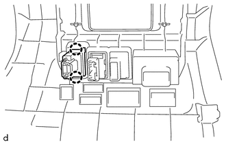
(a) Detach the 2 claws and remove the auto high beam switch from the instrument panel lower finish panel sub-assembly.
 Inspection
INSPECTION
PROCEDURE
1. INSPECT AUTO HIGH BEAM SWITCH
*a
Component without harness connected
(Auto High Beam Switch)
(a) Check the resistance.
(1) Measure the ...
 Installation
INSTALLATION
PROCEDURE
1. INSTALL AUTO HIGH BEAM SWITCH
(a) Attach the 2 claws to install the auto high beam switch to the instrument
panel lower finish panel sub-assembly.
2. INSTALL INSTRUMENT ...
Other materials:
Certification Ecu
Components
COMPONENTS
ILLUSTRATION
Installation
INSTALLATION
PROCEDURE
1. INSTALL CERTIFICATION ECU (SMART KEY ECU ASSEMBLY)
(a) Install the certification ECU (smart key ECU assembly) with the 2 nuts.
Torque:
6.5 N·m {66 kgf·cm, 58 in·lbf}
(b) Engage the clamp to install the wire ...
Power Window Motor Malfunction (B2311)
DESCRIPTION
The power window regulator motor assemblies are operated by the power window
regulator master switch assembly, front power window regulator switch assembly RH.
The power window regulator motor assemblies have motor, regulator and ECU functions.
This DTC is output when the power win ...
Check Mode Procedure
CHECK MODE PROCEDURE
1. DESCRIPTION
(a) Check mode has a higher sensitivity to malfunctions and can detect malfunctions
that normal mode cannot detect. Check mode can also detect all the malfunctions
that normal mode can detect. In check mode, DTCs are detected with 1 trip detection
logic.
...
