Toyota Tacoma (2015-2018) Service Manual: Fuel Pump Ecu
Components
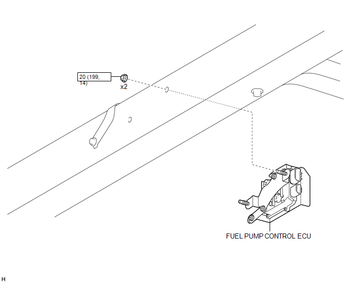
COMPONENTS
ILLUSTRATION
Removal
REMOVAL
PROCEDURE
1. PRECAUTION
NOTICE:
After turning the ignition switch off, waiting time may be required before disconnecting the cable from the battery terminal. Therefore, make sure to read the disconnecting the cable from the battery terminal notice before proceeding with work.
Click here .gif)
2. DISCONNECT CABLE FROM NEGATIVE BATTERY TERMINAL
NOTICE:
When disconnecting the cable, some systems need to be initialized after the cable is reconnected.
Click here
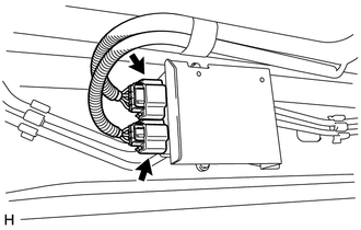
3. REMOVE FUEL PUMP CONTROL ECU
|
(a) Disconnect the 2 connectors. |
|
|
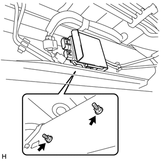
(b) Remove the 2 nuts and fuel pump control ECU. NOTICE: Make sure the fuel pump control ECU is not subjected to physical shocks, such as being dropped, etc. |
|
Installation
INSTALLATION
PROCEDURE
1. INSTALL FUEL PUMP CONTROL ECU
(a) Install the fuel pump control ECU with the 2 bolts.
Torque:
20 N·m {199 kgf·cm, 14 ft·lbf}
NOTICE:
Do not use the fuel pump control ECU if it has been subjected to physical shocks, such as being dropped, etc.
(b) Connect the 2 connectors.
2. CONNECT CABLE TO NEGATIVE BATTERY TERMINAL
Torque:
5.4 N·m {55 kgf·cm, 48 in·lbf}
NOTICE:
When disconnecting the cable, some systems need to be initialized after the cable is reconnected.
Click here .gif)
 Reassembly
REASSEMBLY
CAUTION / NOTICE / HINT
NOTICE:
Do not try to remove the black nylon tube as it is welded to the fuel suction
tube assembly (See page
).
HINT:
Perform "Inspection After Repai ...

Other materials:
Engine Oil Cooler
Components
COMPONENTS
ILLUSTRATION
ILLUSTRATION
ILLUSTRATION
Inspection
INSPECTION
PROCEDURE
1. INSPECT OIL COOLER ASSEMBLY
(a) Check the oil cooler assembly for damage and clogging.
If necessary, replace the oil cooler assembly.
...
Gauges and meters
The following gauges, meters and displays illuminate when the engine switch is
in the ON position.
Tachometer
Displays the engine speed in revolutions per minute.
Speedometer
Displays the vehicle speed.
Engine coolant temperature gauge
Displays the engine coolant temperature.
Fuel gauge
...
TRAC OFF Indicator Light does not Come ON
DESCRIPTION
Refer to TRAC OFF Indicator Light Remains ON (See page
).
WIRING DIAGRAM
Refer to TRAC OFF Indicator Light Remains ON (See page
).
CAUTION / NOTICE / HINT
NOTICE:
When replacing the skid control ECU (master cylinder solenoid), perform
calibration (See page
).
...
