Toyota Tacoma (2015-2018) Service Manual: Installation
INSTALLATION
PROCEDURE
1. INSTALL EXHAUST MANIFOLD SUB-ASSEMBLY LH
(a) Install a new gasket to the cylinder head LH.
NOTICE:
Be careful of the installation direction.
(b) Temporarily install the exhaust manifold sub-assembly LH with the 4 nuts.
|
(c) Tighten the 4 nuts in the sequence shown in the illustration. Torque: 21 N·m {214 kgf·cm, 15 ft·lbf} |
|
2. INSTALL NO. 2 EXHAUST MANIFOLD HEAT INSULATOR
(a) Install the No. 2 exhaust manifold heat insulator to the exhaust manifold sub-assembly LH with the 3 bolts.
Torque:
13 N·m {133 kgf·cm, 10 ft·lbf}
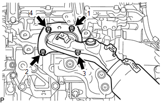
3. INSTALL NO. 2 MANIFOLD STAY
(a) Install the No. 2 manifold stay to the transmission assembly and exhaust manifold sub-assembly LH with the 3 bolts.
Torque:
40 N·m {408 kgf·cm, 30 ft·lbf}
4. INSTALL EXHAUST MANIFOLD SUB-ASSEMBLY RH
(a) Install a new gasket to the cylinder head sub-assembly.
NOTICE:
Be careful of the installation direction.
(b) Temporarily install the exhaust manifold sub-assembly RH with the 4 nuts.
|
(c) Tighten the 4 nuts in the sequence shown in the illustration. Torque: 21 N·m {214 kgf·cm, 15 ft·lbf} |
|
5. INSTALL NO. 1 EXHAUST MANIFOLD HEAT INSULATOR
(a) Install the No. 1 exhaust manifold heat insulator to the exhaust manifold sub-assembly RH with the 3 bolts.
Torque:
13 N·m {133 kgf·cm, 10 ft·lbf}
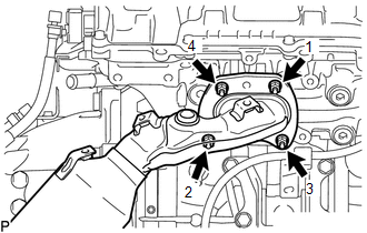
6. INSTALL MANIFOLD STAY
(a) Install the manifold stay to the transmission assembly and exhaust manifold sub-assembly RH with the 3 bolts.
Torque:
40 N·m {408 kgf·cm, 30 ft·lbf}
7. INSTALL AIR FUEL RATIO SENSOR (for Bank 1 Sensor 1)
.gif)
8. INSTALL AIR FUEL RATIO SENSOR (for Bank 2 Sensor 1)
9. INSTALL FRONT NO. 2 EXHAUST PIPE ASSEMBLY
(a) Install the 2 new gaskets to the front No. 2 exhaust pipe assembly.
(b) Connect the front No. 2 exhaust pipe assembly to the exhaust pipe support.
(c) Install the front No. 2 exhaust pipe assembly with the 2 bolts and 2 new nuts.
Torque:
for nut :
54 N·m {554 kgf·cm, 40 ft·lbf}
for bolt :
48 N·m {489 kgf·cm, 35 ft·lbf}
(d) Connect the connector.
10. INSTALL EXHAUST PIPE STOPPER BRACKET (for 4WD)
11. INSTALL CENTER NO. 2 FLOOR HEAT INSULATOR SUB-ASSEMBLY (for 4WD)
12. INSTALL FRONT EXHAUST PIPE ASSEMBLY
|
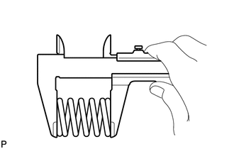
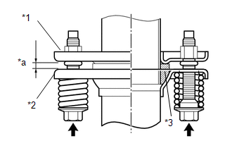
(a) Using a vernier caliper, measure the free length of the compression spring. Minimum free length: 40.5 mm (1.59 in.) If the free length is less than the minimum, replace the compression spring. |
|
(b) Temporarily install a new exhaust pipe gasket to the front exhaust pipe assembly.
|
(c) Using a plastic hammer and wooden block, tap in a new gasket until its surface is flush with the front exhaust pipe assembly. Text in Illustration
NOTICE:
|
|
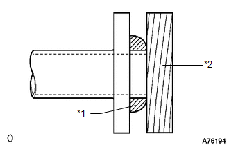
(d) Install a new gasket to the front exhaust pipe assembly.
(e) Install the front exhaust pipe assembly and 2 compression springs with the 2 new nuts.
Torque:
54 N·m {554 kgf·cm, 40 ft·lbf}
|
(f) Install the front exhaust pipe assembly with the 2 compression springs and 2 bolts. Text in Illustration
Torque: 43 N·m {438 kgf·cm, 32 ft·lbf} HINT: After the installation, check that the gaps between the flanges of the front exhaust pipe assembly and center exhaust pipe assembly are consistent front-to-rear and left-to-right. |
|
13. INSTALL FRONT FENDER SEAL LH
(a) Install the front fender seal LH with the 5 clips.
14. INSTALL FRONT FENDER SEAL RH
HINT:
Use the same procedure as for the LH side.
15. INSPECT FOR EXHAUST GAS LEAK
- Perform Inspection After Repair after repairing an exhaust gas leak.
(See page
)
 Components
COMPONENTS
ILLUSTRATION
ILLUSTRATION
...
 Removal
REMOVAL
PROCEDURE
1. REMOVE FRONT FENDER SEAL LH
(a) Remove the 5 clips and front fender seal LH.
2. REMOVE FRONT FENDER SEAL RH
HINT:
Use th ...
Other materials:
Pressure Control Solenoid "A" Circuit Open (P074513)
DESCRIPTION
Changing from 1st to 6th is performed by the ECM turning shift solenoid valves
SL1, SL2, SL3 and SL4 on and off. If an open or short circuit occurs in any of the
shift solenoid valves, the ECM controls the remaining normal shift solenoid valves
to allow the vehicle to be operated ...
Disassembly
DISASSEMBLY
PROCEDURE
1. REMOVE STEERING GEAR OUTLET RETURN TUBE
(a) Using a union nut wrench, remove the steering gear outlet return tube.
2. REMOVE STEERING TURN PRESSURE TUBE
(a) Using a union nut wrench, remove the 2 pressure tubes.
(b) Remove the 4 O-rings from the pressure tubes.
3. ...
Ignition Hold Monitor Malfunction (B2271)
DESCRIPTION
This DTC is stored when a malfunction in the IG circuit or IG hold circuit in
the certification ECU (smart key ECU assembly) is detected.
HINT:
When the cable is disconnected and reconnected to the negative (-) battery terminal,
the power source mode returns to the state it was in ...
