Toyota Tacoma (2015-2018) Service Manual: Inspection
INSPECTION
PROCEDURE
1. INSPECT AUTO HIGH BEAM SWITCH
|
*a |
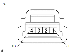
Component without harness connected (Auto High Beam Switch) |
(a) Check the resistance.
(1) Measure the resistance according to the value(s) in the table below.
Standard Resistance:
|
Tester Connection |
Switch Condition |
Specified Condition |
|---|---|---|
| If the result is not as specified, replace the auto high beam switch. | ||
|
4 (+B) - 1 (E) |
Auto high beam switch ON |
Below 1 Ω |
|
Auto high beam switch OFF |
10 kΩ or higher |
|
|
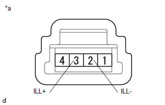
(b) Check the illumination. (1) Apply battery voltage to the connector and check the illumination condition. OK:
|
|
||||||||||
 Components
COMPONENTS
ILLUSTRATION
*A
for Double Cab
*B
for Access Cab
*1
AUTO HIGH BEAM SWITCH
*2
COWL SIDE TRIM ...
 Removal
REMOVAL
PROCEDURE
1. REMOVE FRONT DOOR SCUFF PLATE LH
for Double Cab:
Click here
for Access Cab:
Click here
2. REMOVE COWL SIDE TRIM BOARD LH
Click here
3. REMOVE INSTRUMENT CLUSTER CEN ...
Other materials:
Removal
REMOVAL
PROCEDURE
1. REMOVE FRONT DOOR SCUFF PLATE LH
for Double Cab:
Click here
for Access Cab:
Click here
2. REMOVE COWL SIDE TRIM BOARD LH
Click here
3. REMOVE INSTRUMENT CLUSTER CENTER FINISH PANEL SUB-ASSEMBLY
Click here
4. REMOVE INSTRUMENT CLUSTER FINISH PANEL ASSEMBLY
Cli ...
Fail-safe Chart
FAIL-SAFE CHART
FAIL-SAFE FUNCTION
(a) When a malfunction occurs in the lane departure alert system, a message will
be displayed on the multi-information display in the combination meter assembly
and the lane departure alert system will be disabled depending on the malfunction.
War ...
Utility
UTILITY
NOTICE:
When replacing the millimeter wave radar sensor assembly, always replace
it with a new one. If a millimeter wave radar sensor assembly which was
installed to another vehicle is used, the information stored in it will
not match the information from the vehicle. A ...
