Toyota Tacoma (2015-2018) Service Manual: Removal
REMOVAL
PROCEDURE
1. REMOVE SPIRAL CABLE WITH SENSOR SUB-ASSEMBLY
(See page .gif) )
)
2. REMOVE WINDSHIELD WIPER SWITCH ASSEMBLY
3. REMOVE HEADLIGHT DIMMER SWITCH ASSEMBLY
|
(a) Disconnect the connector. |
|
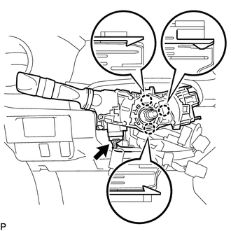
(b) Disengage the 3 claws to remove the headlight dimmer switch assembly.
 Components
COMPONENTS
ILLUSTRATION
...
 Inspection
INSPECTION
PROCEDURE
1. INSPECT HEADLIGHT DIMMER SWITCH ASSEMBLY
(a) Check the resistance.
(1) Measure the resistance according to the value(s) in the table below.
Text in Illustrati ...
Other materials:
Installation
INSTALLATION
PROCEDURE
1. INSTALL REAR SEATBACK HINGE SUB-ASSEMBLY
(a) Install the rear seatback hinge sub-assembly with the 2 bolts.
Torque:
30 N·m {306 kgf·cm, 22 ft·lbf}
2. INSTALL REAR SEATBACK ASSEMBLY
(a) Install the rear seatback assembly with the 2 bolts.
Torque:
37 N·m {377 k ...
Air Conditioning Compressor Magnetic Clutch Circuit
DESCRIPTION
When the air conditioning amplifier assembly is turned on, a magnetic clutch
on signal is sent from the MGC terminal of the air conditioning amplifier assembly.
Then, the MG CLT relay turns on to operate the magnetic clutch assembly.
WIRING DIAGRAM
CAUTION / NOTICE / HINT
NO ...
Problem Symptoms Table
PROBLEM SYMPTOMS TABLE
HINT:
Use the table below to help determine the cause of problem symptoms. If multiple
suspected areas are listed, the potential causes of the symptoms are listed in order
of probability in the "Suspected Area" column of the table. Check each symptom by
check ...
