Toyota Tacoma (2015-2018) Service Manual: Components
COMPONENTS
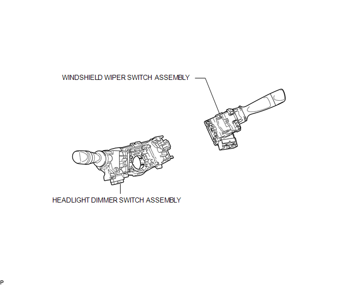
ILLUSTRATION

 Removal
REMOVAL
PROCEDURE
1. REMOVE SPIRAL CABLE WITH SENSOR SUB-ASSEMBLY
(See page )
2. REMOVE WINDSHIELD WIPER SWITCH ASSEMBLY
3. REMOVE HEADLIGHT DIMMER SWITCH ASSEMBLY
(a) Disconnect ...
Other materials:
Stereo Component Amplifier Power Source Circuit
DESCRIPTION
This circuit provides power to the stereo component amplifier assembly.
WIRING DIAGRAM
CAUTION / NOTICE / HINT
Inspect the fuses for circuits related to this system before performing the following
inspection procedure.
PROCEDURE
1.
CHECK HARNESS AND CONNE ...
Air Outlet Damper Control Servo Motor Circuit (B1443/43)
DESCRIPTION
This No. 1 air conditioning radiator damper servo sub-assembly (for mode switching)
is controlled by the air conditioning amplifier assembly and moves the mode damper
to the desired position.
DTC No.
DTC Detection Condition
Trouble Area
...
Vehicle load limits
Vehicle load limits include total load capacity, seating capacity, TWR (Trailer
Weight Rating) and cargo capacity.
■ Total load capacity (vehicle capacity weight):
Total load capacity means the combined weight of occupants, cargo and luggage.
■ Seating capacity:
Regular Cab models ...
