Toyota Tacoma (2015-2018) Service Manual: Disassembly
DISASSEMBLY
CAUTION / NOTICE / HINT
HINT:
- Use the same procedure for the RH side and LH side.
- The following procedure is for the LH side.
- When removing the No. 2 front wheel opening extension pad or No. 1 front wheel opening extension pad or front wheel opening extension pad, heat the front fender wheel opening moulding using a heat light.
- When removing the No. 3 body outside moulding pad or No. 2 body outside moulding pad or No. 1 body outside moulding pad, heat the quarter panel wheel opening moulding using a heat light.
|
Item |
Temperature |
|---|---|
|
Front Fender Wheel Opening Moulding or Quarter Panel Wheel Opening Moulding |
20 to 30°C (68 to 86°F) |
NOTICE:
Do not heat the front fender wheel opening moulding or quarter panel wheel opening moulding excessively.
PROCEDURE
1. REMOVE NO. 2 FRONT WHEEL OPENING EXTENSION PAD
(a) Using a heat light, heat the front fender wheel opening moulding.
|
(b) Remove the No. 2 front wheel opening extension pad. |
|
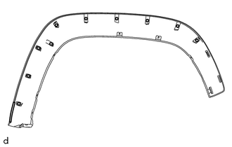
2. REMOVE NO. 1 FRONT WHEEL OPENING EXTENSION PAD
(a) Using a heat light, heat the front fender wheel opening moulding.
|
(b) Remove the No. 1 front wheel opening extension pad. |
|
3. REMOVE FRONT WHEEL OPENING EXTENSION PAD
(a) Using a heat light, heat the front fender wheel opening moulding.
|
(b) Remove the front wheel opening extension pad. |
|
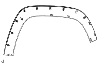
4. REMOVE NO. 3 BODY OUTSIDE MOULDING PAD
(a) Using a heat light, heat the quarter panel wheel opening moulding.
|
(b) Remove the No. 3 body outside moulding pad. |
|
5. REMOVE NO. 2 BODY OUTSIDE MOULDING PAD
(a) Using a heat light, heat the quarter panel wheel opening moulding.
|
(b) Remove the No. 2 body outside moulding pad. |
|
6. REMOVE NO. 1 BODY OUTSIDE MOULDING PAD
(a) Using a heat light, heat the quarter panel wheel opening moulding.
|
(b) Remove the No. 1 body outside moulding pad. |
|
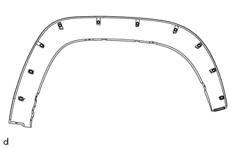
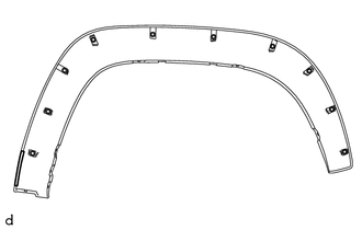
 Components
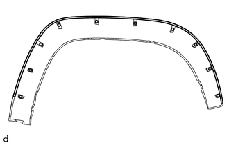
COMPONENTS
ILLUSTRATION
ILLUSTRATION
...
 Reassembly
REASSEMBLY
CAUTION / NOTICE / HINT
HINT:
Use the same procedure for the RH side and LH side.
The following procedure is for the LH side.
When installing a new front wheel opening ex ...
Other materials:
Speed Signal Circuit
DESCRIPTION
The combination meter assembly receives the vehicle speed signal from this circuit.
The wheel speed sensors produce an output that varies according to the vehicle speed.
The wheel speed sensor output is received by the skid control ECU, which uses this
information to create the ve ...
Purge Valve
Components
COMPONENTS
ILLUSTRATION
Inspection
INSPECTION
PROCEDURE
1. INSPECT PURGE VSV
(a) Measure the resistance according to the value(s) in the table below.
Text in Illustration
*a
Component without harness connected
(Purge VSV ...
Yaw Rate Sensor (C1A46)
DESCRIPTION
If the millimeter wave radar sensor assembly receives a yaw rate sensor malfunction
signal from the yaw rate sensor (airbag sensor assembly) or yaw rate sensor zero
point malfunction signal from the skid control ECU (master cylinder solenoid)*1
or skid control ECU (brake actuator ...
