Toyota Tacoma (2015-2018) Service Manual: Removal
REMOVAL
PROCEDURE
1. PRECAUTION
NOTICE:
After turning the ignition switch off, waiting time may be required before disconnecting the cable from the negative (-) battery terminal. Therefore, make sure to read the disconnecting the cable from the negative (-) battery terminal notices before proceeding with work.
Click here .gif)
2. RECOVER REFRIGERANT FROM REFRIGERATION SYSTEM
Click here
3. DISCONNECT CABLE FROM NEGATIVE BATTERY TERMINAL
NOTICE:
When disconnecting the cable, some systems need to be initialized after the cable is reconnected.
Click here
4. REMOVE FAN AND GENERATOR V BELT (for 2TR-FE)
Click here
5. REMOVE GENERATOR ASSEMBLY (for 2GR-FKS)
Click here
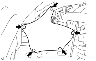
6. REMOVE FRONT UPPER FENDER APRON SEAL
|
(a) Using a clip remover, disengage the 5 clips to remove the front upper fender apron seal. |
|
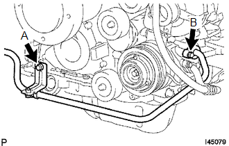
7. DISCONNECT SUCTION HOSE SUB-ASSEMBLY (for 2TR-FE)
(a) Remove the bolt A.
(b) Remove the bolt B to disconnect the suction hose sub-assembly.
(c) Remove the O-ring from the suction hose sub-assembly.
NOTICE:
Seal the opening of the disconnected parts using vinyl tape to prevent moisture and foreign matter from entering.
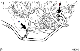
8. DISCONNECT SUCTION HOSE SUB-ASSEMBLY (for 2GR-FKS)
(a) Remove the bolt A.
(b) Remove the bolt A to disconnect the suction hose sub-assembly.
(c) Remove the O-ring from the suction hose sub-assembly.
NOTICE:
Seal the opening of the disconnected parts using vinyl tape to prevent moisture and foreign matter from entering.
9. DISCONNECT DISCHARGE HOSE SUB-ASSEMBLY
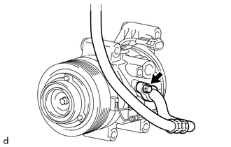
(a) Remove the bolt to disconnect the discharge hose sub-assembly.
(b) Remove the O-ring from the discharge hose sub-assembly.
NOTICE:
Seal the opening of the disconnected parts using vinyl tape to prevent moisture and foreign matter from entering.
10. REMOVE COOLER COMPRESSOR ASSEMBLY (for 2TR-FE)
|
(a) Disconnect the connector. |
|
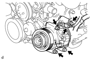
(b) Remove the 2 bolts and 2 nuts.
(c) Using an E8 ''TORX'' socket wrench, remove the 2 stud bolts and cooler compressor assembly.
11. REMOVE COOLER COMPRESSOR ASSEMBLY (for 2GR-FKS)
|
(a) Disconnect the connector. |
|
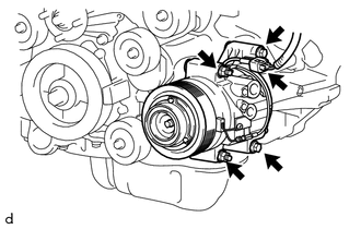
(b) Remove the 2 bolts and 2 nuts.
(c) Using an E8 ''TORX'' socket wrench, remove the 2 stud bolts and cooler compressor assembly.
 Components
COMPONENTS
ILLUSTRATION
ILLUSTRATION
ILLUSTRATION
*1
COMPRESSOR PICK UP SENSOR
*2
MAGNET CLUTCH ASSEMBLY
*3
PRESSURE R ...
 Disassembly
DISASSEMBLY
PROCEDURE
1. REMOVE PRESSURE RELIEF VALVE
(a) Remove the pressure relief valve and O-ring.
2. REMOVE MAGNET CLUTCH ASSEMBLY
(a) Secure the cooler compressor assembly in a vise bet ...
Other materials:
Vehicle Lift And Support Locations
VEHICLE LIFT AND SUPPORT LOCATIONS
1. NOTICE ABOUT VEHICLE CONDITION WHEN JACKING UP VEHICLE
(a) The vehicle must be unloaded before jacking up / lifting up the vehicle.
Never jack up / lift up a heavily loaded vehicle.
(b) When removing heavy parts such as the engine and transmission, the cent ...
Removal
REMOVAL
PROCEDURE
1. REMOVE REAR SEAT CUSHION ASSEMBLY
2. REMOVE NO. 4 ROOM PARTITION COVER LH
3. REMOVE NO. 4 ROOM PARTITION COVER RH
4. REMOVE NO. 3 ROOM PARTITION COVER
5. REMOVE BACK PANEL GARNISH HOLE PLUG
6. REMOVE BACK PANEL TRIM
7. REMOVE FRONT DOOR SCUFF PLATE ...
Inverter Relay
On-vehicle Inspection
ON-VEHICLE INSPECTION
PROCEDURE
1. INSPECT INVERTER RELAY
(a) Check the resistance.
(1) Measure the resistance according to the value(s) in the table below.
Standard Resistance:
Tester Connection
Condition
...
