Toyota Tacoma (2015-2018) Service Manual: Rear Differential Lock Solenoid Circuit High (P17C1)
DESCRIPTION
This DTC is output when a malfunction is detected due to a battery short occurring in the differential lock coil drive circuit of the rear differential.
|
DTC No. |
Detection Item |
DTC Detection Condition |
Trouble Area |
|---|---|---|---|
|
P17C1 |
Rear Differential Lock Solenoid Circuit High |
|
|
WIRING DIAGRAM
Refer to DTC P17C0 (See page .gif) ).
).
PROCEDURE
|
1. |
CHECK DIFFERENTIAL LOCK COIL |
(a) Disconnect the 4 wheel drive control ECU connector.
|
(b) Measure the voltage according to the value(s) in the table below. Standard Voltage:
|
|
| OK | .gif) |
REPLACE 4 WHEEL DRIVE CONTROL ECU |
|
.gif)
|
2. |
CHECK HARNESS AND CONNECTOR (4 WHEEL DRIVE CONTROL ECU - DIFFERENTIAL LOCK COIL) |
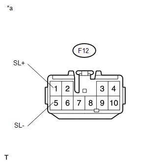
(a) Disconnect the F12 4 wheel drive control ECU connector.
(b) Disconnect the D28 differential lock coil connector.
(c) Measure the voltage according to the value(s) in the table below.
Standard Voltage:
|
Tester Connection |
Switch Condition |
Specified Condition |
|---|---|---|
|
F12-1 (SL+) or D28-2 (SL+) - Body ground |
Ignition switch ON |
Below 1 V |
|
F12-5 (SL-) or D28-1 (SL-) - Body ground |
Ignition switch ON |
Below 1 V |
| OK | |
REPLACE DIFFERENTIAL LOCK COIL |
| NG | |
REPAIR OR REPLACE HARNESS OR CONNECTOR |
 Rear Differential Lock Solenoid Circuit Low (P17C0)
DESCRIPTION
This DTC is output when a malfunction is detected due to a short to ground occurring
in the differential lock coil drive circuit of the rear differential.
DTC No.
...
 Rear Differential Lock Control SW Stuck ON (P17CC)
DESCRIPTION
This DTC is output when a malfunction of the differential lock switch is detected.
DTC No.
Detection Item
DTC Detection Condition
Trouble Area ...
Other materials:
Low Power Supply Voltage Malfunction (C1241)
DESCRIPTION
If there is a problem with the skid control ECU (master cylinder solenoid) power
supply circuit, the skid control ECU outputs the DTC and prohibits operation under
the fail-safe function.
If the voltage supplied to terminal IG1 is not within the DTC detection threshold
due to mal ...
Voice Recognition Microphone Disconnected (B1579)
DESCRIPTION
The navigation receiver assembly and telephone microphone assembly are connected
to each other using the microphone connection detection signal lines.
This DTC is stored when the microphone connection detection signal is disconnected.
DTC Code
DTC Detection Con ...
Air Conditioning Compressor Magnetic Clutch Circuit
DESCRIPTION
When the air conditioning amplifier assembly is turned on, a magnetic clutch
on signal is sent from the MGC terminal of the air conditioning amplifier assembly.
Then, the MG CLT relay turns on to operate the magnetic clutch assembly.
WIRING DIAGRAM
CAUTION / NOTICE / HINT
NO ...
