Toyota Tacoma (2015-2018) Service Manual: Components
COMPONENTS
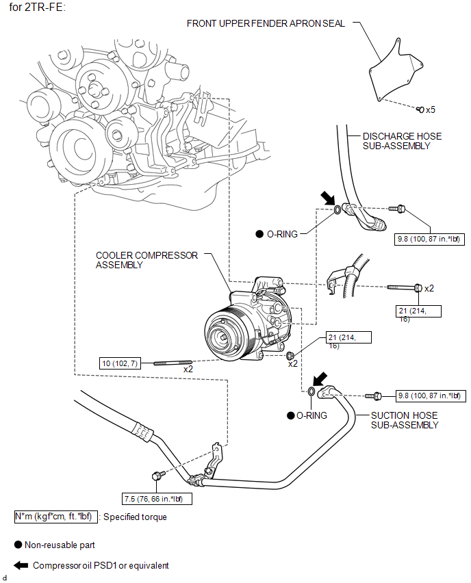
ILLUSTRATION
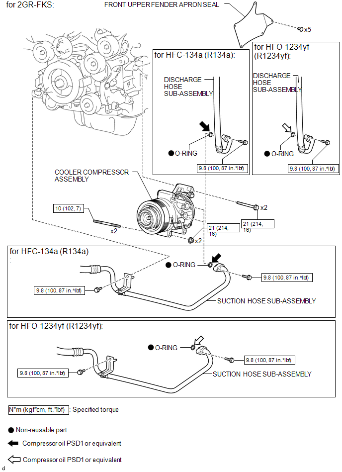
ILLUSTRATION
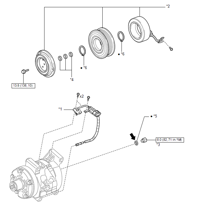
ILLUSTRATION
|
*1 |
COMPRESSOR PICK UP SENSOR |
*2 |
MAGNET CLUTCH ASSEMBLY |
|
*3 |
PRESSURE RELIEF VALVE |
*4 |
COMPRESSOR SPACER |
|
*5 |
O-RING |
*6 |
SNAP RING |
.png) |
N*m (kgf*cm, ft.*lbf): Specified torque |
â—Ź |
Non-reusable part |
.png) |
Compressor oil PSD 1 or equivalent |
- |
- |
 Compressor
...
 Removal
REMOVAL
PROCEDURE
1. PRECAUTION
NOTICE:
After turning the ignition switch off, waiting time may be required before disconnecting
the cable from the negative (-) battery terminal. Therefore, make ...
Other materials:
Freeze Frame Data
FREEZE FRAME DATA
1. FREEZE FRAME DATA
(a) Whenever a DTC is detected, the blind spot monitor sensor stores the current
vehicle (sensor) state as Freeze Frame Data.
2. CHECK FREEZE FRAME DATA
(a) Connect the Techstream to the DLC3.
(b) Turn the ignition switch to ON.
(c) Turn the blind spot ...
Lost Communication with ECM / PCM "A" (U0100,U0125,U0126,U0129)
DESCRIPTION
These DTCs are stored when a communication malfunction occurs between ECUs that
perform pre-collision system control.
DTC No.
Detection Item
DTC Detection Condition
Trouble Area
U0100
Lost Communication with ECM ...
Short in GPS Antenna (B15C0,B15C1)
DESCRIPTION
These DTCs are stored when a malfunction occurs in the navigation antenna assembly.
DTC No.
DTC Detection Condition
Trouble Area
B15C0
Navigation antenna error
Navigation antenna assembly
Radio and ...
