Toyota Tacoma (2015-2018) Service Manual: Initialization
INITIALIZATION
1. ZERO POINT CALIBRATION
NOTICE:
Make sure that the front passenger seat is not occupied before performing the operation.
HINT:
Perform the zero point calibration and sensitivity check if any of the following conditions apply.
- The occupant detection ECU is replaced.
- Accessories (seatback tray and seat cover, etc.) are installed.
- The front passenger seat is removed from the vehicle.
- The passenger airbag ON/OFF indicator (OFF) comes on when the front passenger seat is not occupied.
- An occupant classification sensor collision detection DTC is output due to an accident or a collision.
(a) Zero point calibration and sensitivity check procedures
HINT:
Make sure that the zero point calibration has finished normally, and then perform the sensitivity check.
(1) Adjust the seat position in accordance with the table below.
|
Adjustment Item |
Position |
|---|---|
|
Slide Direction |
Rearmost position |
|
Reclining Angle |
Upright position |
|
Headrest Height |
Lowest position |
|
Lifter Height |
Lowest position |
(2) Connect the Techstream to the DLC3.
(3) Turn the ignition switch to the ON position.
(4) Perform the zero point calibration by following the prompts on the Techstream screen.
HINT:
Refer to the Techstream operator's manual for further details.
OK:
"Zero Point Calibration is complete." is displayed.
(5) Perform the sensitivity check by following the prompts on the Techstream screen.
(6) Confirm that the beginning sensor reading is within the standard range.
Standard range:
-3.2 to 3.2 kg (-7 to 7 lb)
(7) Place a 30 kg (66.1 lb) weight onto the front passenger seat.
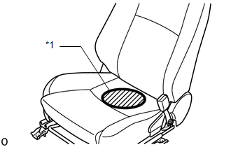
NOTICE:
- Do not allow the weight to come into contact with the seatback when placing it on the seat cushion.
- Place the weight in the area shown in the illustration.
|
*1 |
Weight Position |
(8) Confirm that the sensitivity is within the standard range.
Standard range:
27 to 33 kg (59.52 to 72.75 lb)
HINT:
- When performing the sensitivity check, use a solid metal weight (the check result may not be accurate if a liquid weight is used).
- If the sensitivity deviates from the standard range, retighten the bolts of the front passenger seat taking care not to deform the seat rail. After performing this procedure, if the sensitivity is not within the standard range, replace the front seat with adjuster frame assembly RH.
- If the zero point calibration has not finished normally, replace the front seat with adjuster frame assembly RH.
 How To Proceed With Troubleshooting
PROCEDURE
1.
VEHICLE BROUGHT TO WORKSHOP
NEXT
2.
CUSTOMER PROBLEM ANALYSIS
...
 System Description
SYSTEM DESCRIPTION
1. FRONT PASSENGER OCCUPANT CLASSIFICATION SYSTEM
(a) General Description
(1) The front passenger occupant detection ECU determines whether the front passenger
seat is occupied ...
Other materials:
Removal
REMOVAL
PROCEDURE
1. REMOVE INSTRUMENT PANEL LOWER FINISH PANEL SUB-ASSEMBLY
(See page )
2. REMOVE DRIVER SIDE JUNCTION BLOCK
(a) Disconnect the 5 connectors on the front side.
(b) Remove the 2 nuts to separate the driver side j ...
Problem Symptoms Table
PROBLEM SYMPTOMS TABLE
HINT:
Use the table below to help determine the cause of problem symptoms.
If multiple suspected areas are listed, the potential causes of the symptoms
are listed in order of probability in the "Suspected Area" column of the
table. Check each sy ...
Reassembly
REASSEMBLY
CAUTION / NOTICE / HINT
NOTICE:
Do not try to remove the black nylon tube as it is welded to the fuel suction
tube assembly (See page
).
HINT:
Perform "Inspection After Repairs" after replacing the fuel pump (See page
).
PROCEDURE
1. INSTALL FUEL PUMP
HINT:
Perfo ...
