Toyota Tacoma (2015-2018) Service Manual: Disassembly
DISASSEMBLY
PROCEDURE
1. REMOVE PRESSURE RELIEF VALVE
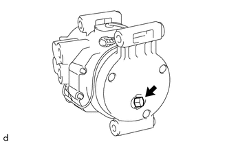
(a) Remove the pressure relief valve and O-ring.
2. REMOVE MAGNET CLUTCH ASSEMBLY
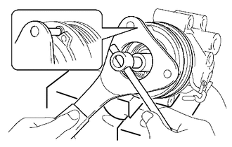
(a) Secure the cooler compressor assembly in a vise between aluminum plates.
(b) Using SST, hold the magnet clutch hub.
SST: 09985-00260
(c) Remove the bolt, magnet clutch hub and compressor spacer.
HINT:
There is no set number of magnet clutch washers since they are used for adjusting.
|
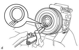
(d) Using a snap ring expander, remove the snap ring and magnet clutch rotor. NOTICE: Do not damage the seal cover of the bearing when removing the snap ring. |
|
|
(e) Remove the screw. |
|
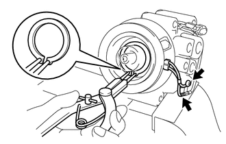
(f) Disconnect the connector.
(g) Using a snap ring expander, remove the snap ring and magnet clutch stator.
3. REMOVE COMPRESSOR PICK UP SENSOR
|
(a) Disengage the clamp. |
|
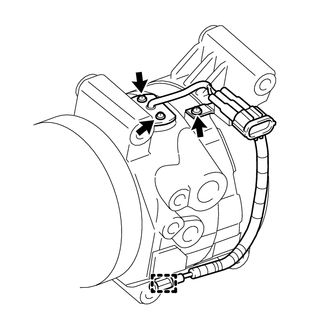
(b) Remove the 3 screws and compressor pick up sensor.
 Removal
REMOVAL
PROCEDURE
1. PRECAUTION
NOTICE:
After turning the ignition switch off, waiting time may be required before disconnecting
the cable from the negative (-) battery terminal. Therefore, make ...
 Inspection
INSPECTION
PROCEDURE
1. INSPECT MAGNET CLUTCH ASSEMBLY
(a) Inspect the magnet clutch assembly.
Text in Illustration
*a
Component without harness c ...
Other materials:
Engine Coolant Temperature Receiver Gauge Malfunction
DESCRIPTION
In this circuit, the meter CPU receives engine coolant temperature signals from
the ECM using the CAN communication system (CAN V1 Bus). The meter CPU displays
engine coolant temperature that is calculated based on the data received from the
ECM.
WIRING DIAGRAM
CAUTION / NOTIC ...
Check Bus 3 Lines for Short Circuit
DESCRIPTION
There may be a short circuit between the CAN main bus lines and/or CAN branch
lines when the resistance between terminals 6 (CA3H) and 21 (CA3L) of the central
gateway ECU (network gateway ECU) is below 54 Ω.
Detection Item
Trouble Area
Resis ...
Heater Circuit (C1AAE)
DESCRIPTION
The forward recognition camera controls the current supplied to the camera heater
(forward recognition hood).
If the forward recognition camera detects a malfunction in the camera heater
(forward recognition hood) circuit, DTC C1AAE is stored.
DTC No.
Detecti ...
