Toyota Tacoma (2015-2018) Service Manual: Removal
REMOVAL
PROCEDURE
1. REMOVE FRONT WHEEL
2. DRAIN DIFFERENTIAL OIL
3. SEPARATE FRONT SPEED SENSOR
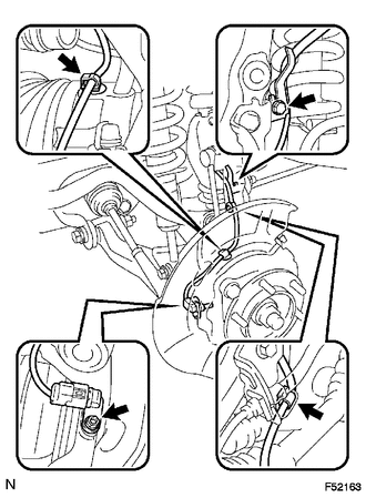
(a) Remove the bolt and separate the front speed sensor.
(b) Disengage the 2 clamps.
(c) Remove the bolt and separate the speed sensor wire harness from the steering knuckle.
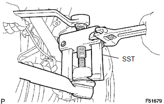
4. SEPARATE TIE ROD END SUB-ASSEMBLY
(a) Remove the cotter pin and nut.
|
(b) Using SST, separate the tie rod end sub-assembly from the steering knuckle. SST: 09628-62011 |
|
5. REMOVE FRONT AXLE HUB NUT
.png)
(a) Using a screwdriver and a hammer, remove the front axle hub grease cap.
|
(b) Remove the cotter pin and adjusting cap. |
|
.png)
(c) Remove the front axle hub nut.
6. SEPARATE FRONT SUSPENSION LOWER ARM
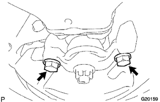
(a) Remove the 2 bolts and separate the front lower ball joint attachment from the steering knuckle.
7. REMOVE FRONT DRIVE SHAFT
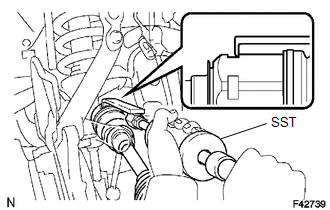
(a) Using SST, remove the front drive shaft.
SST: 09520-01010
SST: 09520-24010
09520-32040
NOTICE:
Be careful not to damage the oil seal.
 Disassembly
DISASSEMBLY
PROCEDURE
1. INSPECT FRONT DRIVE SHAFT
(a) Check whether there is no remarkable play in the outboard joint.
(b) Check whether the inboard joint slides smoothly in the thrust directio ...
 Installation
INSTALLATION
PROCEDURE
1. INSTALL FRONT DRIVE SHAFT
(a) Coat the spline of the inboard joint shaft with gear oil.
(b) Align the shaft splines and install the front drive shaft with a brass bar
...
Other materials:
Diagnosis System
DIAGNOSIS SYSTEM
CHECK DLC3
(a) Check the DLC3.
Click here
FUNCTION OF WARNING INDICATOR AND MESSAGE
(a) If the lane departure alert system is not functioning properly, the driver
is warned by the lane departure alert indicator and multi-information display warning
message on the combinat ...
Installation
INSTALLATION
PROCEDURE
1. INSTALL NO. 1 ULTRASONIC SENSOR
HINT:
Use the same procedure for both sides.
(a) Engage the 4 claws to install the 4 No. 1 ultrasonic sensors as shown in
the illustration.
2. INSTALL REAR BUMPER EXTENSION LH (w/ Towing Package)
(See page )
3. INSTALL REAR BUMPE ...
Parking Brake Lever
Components
COMPONENTS
ILLUSTRATION
ILLUSTRATION
Installation
INSTALLATION
PROCEDURE
1. INSTALL PARKING BRAKE SWITCH ASSEMBLY
2. INSTALL PARKING BRAKE LEVER SUB-ASSEMBLY
(a) Install the 2 toothed washers and parking brake lever support to the parking
brake lever.
(b) Install th ...
