Toyota Tacoma (2015-2018) Service Manual: Disassembly
DISASSEMBLY
CAUTION / NOTICE / HINT
CAUTION:
Wear protective gloves. Sharp areas on the parts may injure your hands.
PROCEDURE
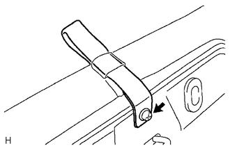
1. REMOVE REAR SEAT CUSHION BAND
|
(a) Remove the screw and rear seat cushion band. |
|
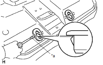
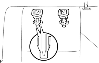
2. REMOVE REAR SEAT HEADREST HOLDER
|
(a) Using a screwdriver with its tip taped in protective tape, disengage the 4 claws to remove the 2 rear seat headrest holders. Text in Illustration
|
|
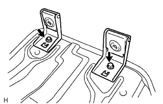
3. REMOVE REAR SEAT CUSHION HINGE SUB-ASSEMBLY
|
(a) Remove the 2 bolts and 2 rear seat cushion hinge sub-assemblies. |
|
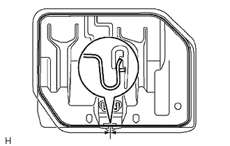
4. REMOVE REAR SEAT CUSHION FRAME SUB-ASSEMBLY
|
(a) Disengage the hook to remove the rear seat cushion frame sub-assembly. |
|
5. REMOVE SEPARATE TYPE REAR SEAT CUSHION COVER
|
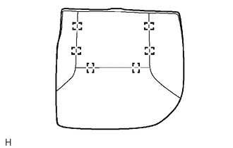
(a) Remove the 6 hog rings and separate type rear seat cushion cover. |
|
6. REMOVE REAR SEAT HEADREST ASSEMBLY
(a) Disengage the 2 lock buttons of the 2 rear seat headrest supports to remove the rear seat headrest assembly.
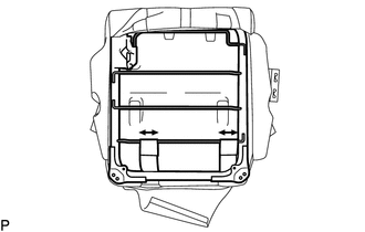
7. REMOVE REAR SEATBACK BOARD SUB-ASSEMBLY
|
(a) Remove the 2 screws. |
|
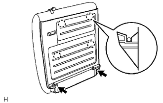
(b) Disengage the 4 claws to remove the rear seatback board sub-assembly.
8. REMOVE REAR SEAT HEADREST SUPPORT
|
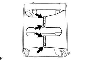
(a) Disconnect the 2 rear seatback cover straps. |
|
|
(b) Disengage the 2 hooks. |
|
|
(c) Disengage the 4 claws and remove the 2 rear seat headrest supports. |
|
9. REMOVE REAR SEATBACK FRAME SUB-ASSEMBLY
|
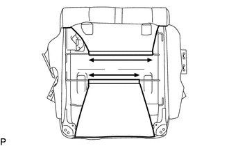
(a) Disengage the 2 hooks to remove the rear seatback frame sub-assembly. |
|
10. REMOVE REAR SEATBACK LOCK ASSEMBLY
|
(a) Remove the 2 bolts and rear seatback lock assembly. |
|
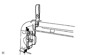
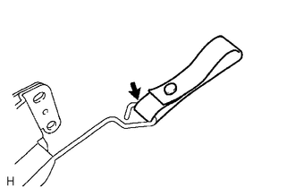
11. REMOVE REAR SEAT LOCK HANDLE
|
(a) Remove the rear seat lock handle from the rear seatback lock. |
|
12. REMOVE SEPARATE TYPE REAR SEATBACK COVER
|
(a) Disengage the 2 hook-and-loop fasteners. |
|
(b) Remove the 2 hog rings and separate type rear seatback cover.
 Removal
REMOVAL
PROCEDURE
1. REMOVE REAR SEAT CUSHION ASSEMBLY
(a) Remove the 2 bolts and rear seat cushion assembly.
2. REMOVE REAR SEATBACK HINGE COV ...
 Installation
INSTALLATION
PROCEDURE
1. INSTALL REAR SEATBACK CENTER HINGE SUB-ASSEMBLY
(a) Install the rear seatback center hinge sub-assembly with the 2 bolts.
Torque:
30 N·m {306 kgf·cm, 22 ft·lbf}
2. ...
Other materials:
Inner Rear View Mirror
Components
COMPONENTS
ILLUSTRATION
ILLUSTRATION
Calibration
CALIBRATION
1. SELECT COMPASS DISPLAY MODE
(a) The compass switch allows you to select the Display or Non-display mode of
the compass.
*1
Compass Switch / EC Control Switch
2. PERFORM CALI ...
Disassembly
DISASSEMBLY
PROCEDURE
1. REMOVE TAIL GATE PROTECTOR
(See page )
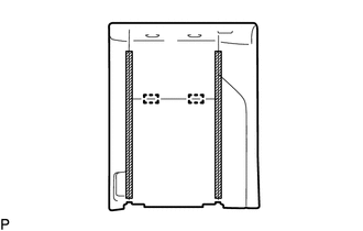
2. REMOVE TAIL GATE SERVICE HOLE COVER
(a) Using a T30 "TORX" socket wrench, remove the 8 screws and tail gate
service hole cover.
3. REMOVE REAR TELEVISION CAMER ...
Transmitter ID1 Error (C2141/41-C2144/44)
DESCRIPTION
The tire pressure warning valve and transmitters that are installed in the tire
and wheel assemblies measure the tire pressure of each wheel. The measured values
are transmitted to the tire pressure warning ECU and receiver in the vehicle as
radio waves. The ECU compares the measu ...
