Toyota Tacoma (2015-2018) Service Manual: Installation
INSTALLATION
PROCEDURE
1. INSTALL FRONT DRIVE SHAFT
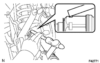
(a) Coat the spline of the inboard joint shaft with gear oil.
(b) Align the shaft splines and install the front drive shaft with a brass bar and hammer.
NOTICE:
- Set the snap ring with the opening side facing downward.
- Be careful not to damage the oil seal.
HINT:
Whether the inboard joint shaft is in contact with the pinion shaft or not can be confirmed from the sound or feeling when driving it.
2. INSTALL FRONT SUSPENSION LOWER ARM
(a) Install the front lower ball joint attachment with the 2 bolts.
Torque:
160 N·m {1631 kgf·cm, 118 ft·lbf}
3. INSTALL FRONT AXLE HUB NUT
(a) Install the front axle hub nut.
Torque:
235 N·m {2396 kgf·cm, 173 ft·lbf}
(b) Install the adjusting cap and a new cotter pin.
(c) Install the front axle hub grease cap.
4. INSTALL TIE ROD END SUB-ASSEMBLY
(a) Install the tie rod end sub-assembly to the steering knuckle.
(b) Install the nut.
Torque:
91 N·m {928 kgf·cm, 67 ft·lbf}
(c) Install a new cotter pin.
5. INSTALL FRONT SPEED SENSOR
(a) Install the speed sensor wire harness to the steering knuckle with the bolt.
Torque:
13 N·m {133 kgf·cm, 10 ft·lbf}
(b) Engage the 2 clamps.
(c) Install the front speed sensor with the bolt.
Torque:
8.3 N·m {85 kgf·cm, 73 in·lbf}
6. INSTALL FRONT WHEEL
Torque:
113 N·m {1152 kgf·cm, 83 ft·lbf}
7. ADD DIFFERENTIAL OIL
.gif)
8. INSPECT DIFFERENTIAL OIL
9. INSPECT SPEED SENSOR SIGNAL (for Hydraulic Brake Booster)
(See page )
10. INSPECT SPEED SENSOR SIGNAL (for Vacuum Brake Booster)
(See page )
11. INSPECT FOR DIFFERENTIAL OIL LEAK
12. INSPECT AND ADJUST FRONT WHEEL ALIGNMENT
(See page )
 Removal
REMOVAL
PROCEDURE
1. REMOVE FRONT WHEEL
2. DRAIN DIFFERENTIAL OIL
3. SEPARATE FRONT SPEED SENSOR
(a) Remove the bolt and separate the front speed sensor.
(b) Disengage the 2 clamps.
(c) Remov ...
 Propeller Shaft
...
Other materials:
Playing an audio CD and MP3/WMA/AAC discs
Insert disc or select “CD” on the “Select Audio Source” screen to begin listening
to a CD.
Audio control screen
1. “Select Audio Source” screen appears
2. Audio CD
Displaying the track list
MP3/WMA/AAC
Displaying the folder list
3. Random playback
4. Repeat play
5. Pause
...
Road Test
ROAD TEST
PROBLEM SYMPTOM CONFIRMATION
HINT:
The dynamic radar cruise control system has 2 cruise control modes:
constant speed control mode and vehicle-to-vehicle distance control mode.
Vehicle-to-vehicle distance control mode is selected by default when
the dyna ...
Pressure Sensor Circuit (B1423)
DESCRIPTION
This DTC is stored if refrigerant pressure on the high pressure side is extremely
low (176 kPa (1.8 kgf/cm2, 26 psi) or less) or extremely high (3140 kPa (32.0 kgf/cm2,
455 psi) or more). The air conditioner pressure sensor, which is installed on the
pipe on the high pressure side ...
