Toyota Tacoma (2015-2018) Service Manual: Daytime Running Light Relay Circuit
DESCRIPTION
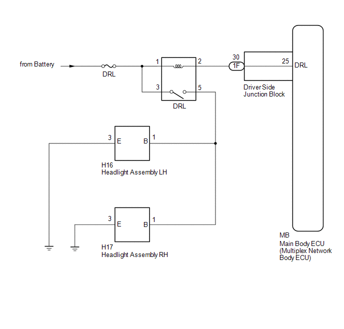
The main body ECU (multiplex network body ECU) controls the daytime running lights.
WIRING DIAGRAM
CAUTION / NOTICE / HINT
NOTICE:
- Inspect the fuses for circuits related to this system before performing the following inspection procedure.
- If the main body ECU (multiplex network body ECU) is replaced, refer
to Registration (See page
.gif) ).*1
).*1
- *1: w/ Smart Key System
PROCEDURE
|
1. |
PERFORM ACTIVE TEST USING TECHSTREAM (DAYTIME RUNNING LIGHT) |
(a) Connect the Techstream to the DLC3.
(b) Turn the ignition switch to ON.
(c) Turn the Techstream on.
(d) Enter the following menus: Body Electrical / Main Body / Active Test.
(e) Perform the Active Test according to the display on the Techstream.
Main Body|
Tester Display |
Test Part |
Control Range |
Diagnostic Note |
|---|---|---|---|
|
Daytime Running Light |
Daytime running lights |
ON/OFF |
- |
OK:
Daytime running lights illuminate.
| OK | .gif) |
PROCEED TO NEXT SUSPECTED AREA SHOWN IN PROBLEM SYMPTOMS TABLE |
|
.gif)
|
2. |
INSPECT RUNNING LIGHT RELAY (DRL) |
|
(a) Remove the running light relay. |
|
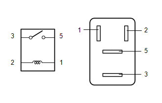
(b) Measure the resistance according to the value(s) in the table below.
Standard Resistance:
|
Tester Connection |
Condition |
Specified Condition |
|---|---|---|
|
3 - 5 |
Battery voltage not applied to terminals 1 and 2 |
10 kΩ or higher |
|
3 - 5 |
Battery voltage applied to terminals 1 and 2 |
Below 1 Ω |
| NG | |
REPLACE RUNNING LIGHT RELAY |
|
|
3. |
CHECK HARNESS AND CONNECTOR (BATTERY - RUNNING LIGHT RELAY) |
(a) Measure the voltage according to the value(s) in the table below.
Standard Voltage:
|
Tester Connection |
Condition |
Specified Condition |
|---|---|---|
|
Relay terminal 1 - Body ground |
Always |
11 to 14 V |
|
Relay terminal 3 - Body ground |
Always |
11 to 14 V |
| NG | |
REPAIR OR REPLACE HARNESS OR CONNECTOR |
|
|
4. |
CHECK HARNESS AND CONNECTOR (RUNNING LIGHT RELAY - DRIVER SIDE JUNCTION BLOCK AND BODY GROUND) |
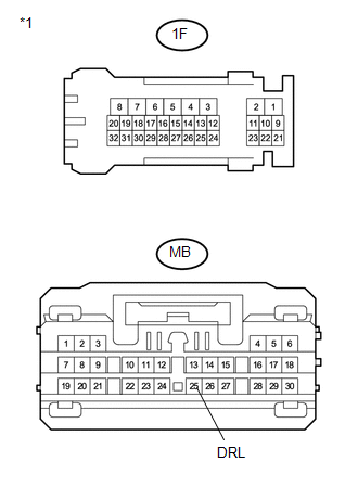
(a) Disconnect the 1F driver side junction block connector.
(b) Measure the resistance according to the value(s) in the table below.
Standard Resistance:
|
Tester Connection |
Condition |
Specified Condition |
|---|---|---|
|
Running light relay terminal 2 - 1F-30 |
Always |
Below 1 Ω |
|
1F-30 - Body ground |
Always |
10 kΩ or higher |
| NG | |
REPAIR OR REPLACE HARNESS OR CONNECTOR |
|
|
5. |
INSPECT DRIVER SIDE JUNCTION BLOCK |
|
(a) Remove the driver side junction block. |
|
(b) Measure the resistance according to the value(s) in the table below.
Standard Resistance:
|
Tester Connection |
Condition |
Specified Condition |
|---|---|---|
|
1F-30 - MB-25 (DRL) |
Always |
Below 1 Ω |
|
1F-30 - Body ground |
Always |
10 kΩ or higher |
|
*1 |
Component without harness connected (Driver Side Junction Block) |
| OK | |
PROCEED TO NEXT SUSPECTED AREA SHOWN IN PROBLEM SYMPTOMS TABLE |
| NG | |
REPLACE DRIVER SIDE JUNCTION BLOCK |
 ACC Signal Circuit
DESCRIPTION
This circuit detects whether the ignition switch is ACC or off, and sends this
information to the main body ECU (multiplex network body ECU).
WIRING DIAGRAM
CAUTION / NOTICE / HINT
...
 Headlight Dimmer Switch Circuit
DESCRIPTION
The main body ECU (multiplex network body ECU) receives the following switch
information:
Light control switch position is off (DRL OFF), tail, head or AUTO (DRL).
Dimmer ...
Other materials:
How To Proceed With Troubleshooting
CAUTION / NOTICE / HINT
HINT:
*: Use the Techstream.
PROCEDURE
1.
VEHICLE BROUGHT TO WORKSHOP
NEXT
2.
CUSTOMER PROBLEM ANALYSIS
Click here
(a) Confirm problem s ...
Windshield wipers and washer
■ Without intermittent type
Type A
Low speed windshield wiper
operation
High speed windshield wiper operation
Temporary operation
Washer operation
Type B
Low speed windshield wiper operation
High speed windshield wiper operation
Temporary operation
Washer op ...
Reassembly
REASSEMBLY
CAUTION / NOTICE / HINT
NOTICE:
When installing the hood bulge protector, heat the hood bulge surface
using the infrared light.
Do not heat the hood bulge excessively.
Item
Temperature
Hood Bulge
...
