Toyota Tacoma manuals

Toyota Tacoma (2015-2018) Service Manual: Removal

REMOVAL

CAUTION / NOTICE / HINT

Text in Illustration

*a

Object Exceeding Weight Limit of Transmission Jack

  • Be sure to perform this procedure with several people as the rear differential carrier assembly is very heavy.
  • Be sure to follow the procedure described in the repair manual, or the transmission jack may suddenly drop or a part may fall.

HINT:

The following procedures are for BD22 (w/o Differential Lock).

PROCEDURE

1. REMOVE REAR WHEELS

2. REMOVE REAR PROPELLER SHAFT ASSEMBLY (for 2WD)

(See page 3. REMOVE REAR PROPELLER SHAFT ASSEMBLY (for 4WD) )

3. REMOVE REAR PROPELLER SHAFT ASSEMBLY (for 4WD)

(See page 4. DRAIN DIFFERENTIAL OIL )

4. DRAIN DIFFERENTIAL OIL

(See page 5. REMOVE REAR AXLE SHAFT WITH BACKING PLATE LH )

5. REMOVE REAR AXLE SHAFT WITH BACKING PLATE LH

(See page 6. REMOVE REAR AXLE SHAFT WITH BACKING PLATE RH 6. REMOVE REAR AXLE SHAFT WITH BACKING PLATE RH )

6. REMOVE REAR AXLE SHAFT WITH BACKING PLATE RH

HINT:

Use the same procedure described for the LH side.

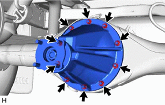
7. REMOVE REAR DIFFERENTIAL CARRIER ASSEMBLY

(a) Remove the 10 nuts, 10 washers and rear differential carrier assembly.

CAUTION:

The rear differential carrier assembly is a heavy component. Make sure that it is supported securely.

NOTICE:

  • Securely support the rear differential carrier assembly while performing this step to avoid excessively tilting or dropping the rear differential carrier assembly.
  • The remaining oil may leak out when removing the rear differential carrier assembly.
  • Do not damage the installation surface when removing the rear differential carrier assembly.
  • Remove the bolts with the rear differential carrier assembly secured.

8. REMOVE REAR DIFFERENTIAL CARRIER GASKET

Components
COMPONENTS ILLUSTRATION HINT: The following specifications are for BD22A (w/o Differential Lock). BD22A differentials are equipped with M10 rear differential carrier to rear axel housing fastener ...

Inspection
INSPECTION PROCEDURE 1. INSPECT DIFFERENTIAL PINION AND SIDE GEAR (a) Check that there is no damage to the pinion gear or side gear. If the pinion gear and/or side gear is damaged, replace the dif ...

Other materials:

Inspection
INSPECTION PROCEDURE 1. INSPECT TIE ROD END SUB-ASSEMBLY (a) Flip the ball joint stud back and forth 5 times as shown in the illustration before installing the nut. (b) Using a torque wrench, turn the nut continuously at a rate of 2 to 4 seconds per turn and check the torque reading on the ...

Short to GND in Immobiliser System Power Source Circuit (B278A)
DESCRIPTION When there is a short to GND in the power supply for the transponder key amplifier of the engine switch, the certification ECU (smart key ECU assembly) stores this DTC. DTC Code DTC Detection Condition Trouble Area DTC Output Confirmation ...

Check Bus 3 Line for Short to +B
DESCRIPTION There may be a short circuit between one of the CAN bus lines and +B when no resistance exists between terminal 6 (CA3H) of the central gateway ECU (network gateway ECU) and terminal 16 (BAT) of the DLC3, or terminal 21 (CA3L) of the central gateway ECU (network gateway ECU) and t ...

В© 2011-2026 Copyright www.ttguide.net