Toyota Tacoma (2015-2018) Service Manual: Reassembly
REASSEMBLY
CAUTION / NOTICE / HINT
HINT:
The procedure described below is for the LH side. Use the same procedure for both the LH and RH sides, unless otherwise specified.
PROCEDURE
1. INSTALL REAR SEAT CUSHION FRAME SUB-ASSEMBLY
|
(a) Install the rear seat cushion frame sub-assembly to the rear seat cushion pad. |
|
.png)
2. INSTALL SEPARATE TYPE REAR SEAT CUSHION COVER
|
(a) Install the separate type rear seat cushion cover. |
|
.png)
(b) Engage the hook.
3. INSTALL REAR SEAT LOCK ASSEMBLY
|
(a) Temporarily install the rear seat lock assembly with the bolt. |
|
.png)
4. INSTALL REAR SEAT CUSHION SUPPORT BRACKET SUB-ASSEMBLY
|
(a) Temporarily install the rear seat cushion support bracket sub-assembly with the 2 bolts. |
|
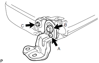
(b) Using T30 "TORX" socket wrench, tighten bolt A.
Torque:
13 N·m {133 kgf·cm, 10 ft·lbf}
(c) Tighten bolt B.
Torque:
18 N·m {184 kgf·cm, 13 ft·lbf}
(d) Tighten bolt C.
Torque:
7.0 N·m {71 kgf·cm, 62 in·lbf}
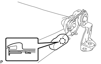
5. INSTALL REAR SEAT LOCK HANDLE
|
(a) Engage the claw and install the rear seat lock handle. |
|
6. INSTALL REAR SEAT HINGE SUB-ASSEMBLY
|
(a) Install the rear seat hinge sub-assembly with the bolt. Torque: 18 N·m {184 kgf·cm, 13 ft·lbf} |
|
.png)
7. INSTALL REAR SEAT CUSHION COVER
|
(a) Install the rear seat cushion cover with the screw. |
|
.png)
8. INSTALL REAR SEAT CUSHION UNDER COVER
|
(a) Install the rear seat cushion under cover with the screw. |
|
.png)
9. INSTALL REAR SEATBACK LOCK COVER
|
(a) Install the rear seatback lock cover with the 2 screws. |
|
.png)
10. INSTALL REAR SEATBACK COVER
|
(a) Engage the 2 claws and install the rear seatback cover. |
|
.png)
(b) Install the 2 screws.
 Disassembly
DISASSEMBLY
CAUTION / NOTICE / HINT
HINT:
The procedure described below is for the LH side. Use the same procedure for
both the LH and RH sides, unless otherwise specified.
PROCEDURE
1. REMOVE ...
 Removal
REMOVAL
PROCEDURE
1. REMOVE REAR SEAT CUSHION ASSEMBLY
(a) Remove the 6 bolts and 2 rear seat cushion assemblies.
2. REMOVE NO. 4 ROOM PARTITIO ...
Other materials:
Installation
INSTALLATION
CAUTION / NOTICE / HINT
HINT:
Use the same procedure for the RH side and LH side.
The procedure listed below is for the LH side.
PROCEDURE
1. INSTALL FRONT COIL SPRING
(a) Install SST to the front coil spring, and secure SST in a vise.
SST: 09727-00 ...
Short in Curtain Shield Squib RH Circuit (B1830/57-B1833/57)
DESCRIPTION
The front passenger side curtain shield squib circuit consists of the airbag
sensor assembly and the curtain shield airbag assembly RH.
The circuit signals the SRS to deploy when airbag deployment conditions are met.
These DTCs are set when a malfunction is detected in the front pas ...
System Voltage Circuit Short to Ground or Open (P056014)
DESCRIPTION
The battery supplies power to the ECM even when the ignition switch is off. This
power allows the ECM to store data such as DTC history, freeze frame data and fuel
trim values. If the battery voltage falls below a minimum level, the ECM data is
cleared and the ECM determines that ...
