Toyota Tacoma (2015-2018) Service Manual: Installation
INSTALLATION
PROCEDURE
1. INSTALL REAR AXLE SHAFT OIL SEAL
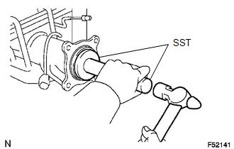
(a) Using SST and a hammer, install a new oil seal.
SST: 09950-60020
09951-00770
SST: 09950-70010
09951-07150
2. INSTALL REAR AXLE SHAFT WITH BACKING PLATE
.png)
(a) Install a new O-ring.
(b) Install the rear axle shaft with backing plate with the 4 nuts.
Torque:
45 N·m {459 kgf·cm, 33 ft·lbf}
3. INSTALL REAR BRAKE TUBE NO. 8
.png)
(a) Using a union nut wrench, connect the brake tube.
Torque:
15 N·m {155 kgf·cm, 11 ft·lbf}
4. INSTALL PARKING BRAKE CABLE ASSEMBLY NO. 3
.png)
(a) Install the parking brake cable with the 2 bolts onto the backing plate.
Torque:
8.0 N·m {82 kgf·cm, 71 in·lbf}
5. INSTALL REAR SPEED SENSOR
Click here .gif)
6. APPLY HIGH TEMPERATURE GREASE
Click here
7. INSTALL REAR BRAKE SHOE
Click here
8. INSTALL FRONT BRAKE SHOE
Click here
9. INSPECT REAR DRUM BRAKE INSTALLATION
Click here
10. INSTALL REAR BRAKE DRUM SUB-ASSEMBLY
Click here
11. ADJUST REAR DRUM BRAKE SHOE CLEARANCE
Click here
12. INSTALL REAR WHEEL
Torque:
113 N·m {1152 kgf·cm, 83 ft·lbf}
13. CONNECT CABLE TO NEGATIVE BATTERY TERMINAL
Torque:
5.4 N·m {55 kgf·cm, 48 in·lbf}
NOTICE:
When disconnecting the cable, some systems need to be initialized after the cable is reconnected.
Click here
14. FILL RESERVOIR WITH BRAKE FLUID (for Hydraulic Brake Booster)
Click here
15. FILL RESERVOIR WITH BRAKE FLUID (for Vacuum Brake Booster)
Click here
16. BLEED MASTER CYLINDER (for Vacuum Brake Booster)
Click here
17. BLEED BRAKE LINE (for Hydraulic Brake Booster)
Click here
18. BLEED BRAKE LINE (for Vacuum Brake Booster)
Click here
19. INSPECT FLUID LEVEL IN RESERVOIR (for Hydraulic Brake Booster)
Click here
20. INSPECT FLUID LEVEL IN RESERVOIR (for Vacuum Brake Booster)
Click here
21. INSPECT FOR BRAKE FLUID LEAK
22. INSPECT PARKING BRAKE LEVER TRAVEL
Click here
23. ADJUST PARKING BRAKE LEVER TRAVEL
Click here
24. CHECK VSC SENSOR SIGNAL (for Hydraulic Brake Booster)
Click here
25. CHECK VSC SENSOR SIGNAL (for Vacuum Brake Booster)
Click here
 Removal
REMOVAL
PROCEDURE
1. PRECAUTION
NOTICE:
After turning the ignition switch off, waiting time may be required before disconnecting
the cable from the negative (-) battery terminal.
Therefore, mak ...
 Reassembly
REASSEMBLY
PROCEDURE
1. INSTALL REAR AXLE HUB BOLT
(a) Install a new deflector gasket and deflector onto the rear axle shaft.
HINT:
Align the 2 notches.
...
Other materials:
Pattern Select Switch Power Mode Circuit
DESCRIPTION
The ECM memory contains the programs for the normal and PWR shift patterns.
By following the programs corresponding to the signals from the pattern select
switch assembly, park/neutral position switch and other various sensors, the ECM
switches the shift solenoid valves on and off, ...
Display does not Dim when Light Control Switch is Turned ON
PROCEDURE
1.
CHECK IMAGE QUALITY SETTING
(a) Display the "Display" screen.
(b) Turn the light control switch to the tail or head position.
(c) Check if "Day Mode" on the display adjustment screen is on.
OK:
"Day Mode" setting is of ...
Confirm Cellular Phone Functionality
PROCEDURE
1.
CHECK CUSTOMER'S CELLULAR PHONE COMPATIBILITY
(a) Check if the cellular phone is compatible (Refer to http://www.toyota.com/entune/).
Result
Result
Proceed to
Cellular phone is compatible
A
...
