Toyota Tacoma (2015-2018) Service Manual: Crawl Indicator Light Remains ON
DESCRIPTION
When CRAWL starts after operating the CRAWL switch (drive monitor switch), the CRAWL indicator light turns on. While CRAWL is in the process of stopping, the CRAWL indicator light begins blinking. When CRAWL totally stops, the CRAWL indicator light turns off.
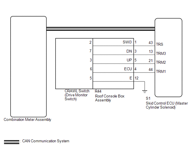
WIRING DIAGRAM
CAUTION / NOTICE / HINT
NOTICE:
- When replacing the skid control ECU (master cylinder solenoid), perform
calibration (See page
.gif) ).
). - Inspect the fuses for circuits related to this system before performing the following inspection procedure.
PROCEDURE
|
1. |
CHECK CAN COMMUNICATION SYSTEM |
(a) Turn the ignition switch off.
(b) Connect the Techstream to the DLC3.
(c) Turn the ignition switch to ON.
(d) Turn the Techstream on.
(e) Select CAN Bus Check from the System Selection Menu screen and follow the
prompts on the screen to inspect the CAN bus (See page
).
OK:
CAN Bus Check indicates no malfunctions in CAN communication.
| NG | .gif) |
GO TO CAN COMMUNICATION SYSTEM (HOW TO PROCEED WITH TROUBLESHOOTING) |
|
.gif)
|
2. |
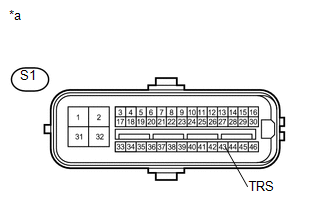
INSPECT SKID CONTROL ECU (TRS TERMINAL) |
(a) Disconnect the S1 skid control ECU (master cylinder solenoid) connector.
|
(b) Measure the resistance according to the value(s) in the table below. Standard Resistance:
|
|
(c) Reconnect the S1 skid control ECU (master cylinder solenoid) connector.
| NG | |
GO TO STEP 4 |
|
|
3. |
READ VALUE USING TECHSTREAM (CRAWL CONTROL LIGHT) |
(a) Turn the ignition switch off.
(b) Connect the Techstream to the DLC3.
(c) Turn the ignition switch to ON.
(d) Turn the Techstream on.
(e) Enter the following menus: Chassis / ABS/VSC/TRAC / Active Test.
(f) According to the display on the Techstream, read the Data List.
ABS/VSC/TRAC|
Tester Display |
Measurement Item/Range |
Normal Condition |
Diagnostic Note |
|---|---|---|---|
|
Crawl Control Light |
Crawl indicator light/ ON or OFF |
ON: Indicator light on OFF: Indicator light off |
- |
(g) Check the Techstream display condition of the brake warning light.
Result|
Result |
Proceed to |
|---|---|
|
Display of the Data List remains OFF |
A |
|
Display of the Data List remains ON |
B |
| A | |
GO TO METER / GAUGE SYSTEM |
| B | |
REPLACE MASTER CYLINDER SOLENOID |
|
4. |
INSPECT DRIVE MONITOR SWITCH |
(a) Remove the crawl control switch (drive monitor switch) (See page
).
(b) Inspect the crawl control switch (drive monitor switch) (See page
).
| NG | |
REPLACE DRIVE MONITOR SWITCH |
|
|
5. |
INSPECT ROOF CONSOLE BOX ASSEMBLY |
(a) Remove the roof console box assembly.
- for Double Cab: (See page
)
- for Access Cab: (See page
)
.png) Text in Illustration
Text in Illustration
|
*a |
Component without harness connected (Roof Console Box Assembly) |
- |
- |
(b) Measure the resistance according the value(s) in the table below.
Standard Resistance:
|
Tester Connection |
Condition |
Specified Condition |
|---|---|---|
|
R44-1 (SWI3) - 2 |
Always |
Below 1 Ω |
|
R44-3 (DN) - 7 |
Always |
Below 1 Ω |
|
R44-4 (ECU) - 6 |
Always |
Below 1 Ω |
|
R44-5 (UP) - 3 |
Always |
Below 1 Ω |
|
R44-12 (GND) - 5 |
Always |
Below 1 Ω |
|
Result |
Proceed to |
|---|---|
|
OK |
A |
|
NG (for Double Cab) |
B |
|
NG (for Access Cab) |
C |
| A | |
REPAIR OR REPLACE HARNESS OR CONNECTOR (MASTER CYLINDER SOLENOID - ROOF CONSOLE BOX ASSEMBLY) |
| B | |
REPLACE ROOF CONSOLE BOX ASSEMBLY |
| C | |
REPLACE ROOF CONSOLE BOX ASSEMBLY |
 Crawl Indicator Light does not Come ON
DESCRIPTION
Refer to Crawl Indicator Light Remains ON (See page
).
WIRING DIAGRAM
Refer to Crawl Indicator Light Remains ON (See page
).
CAUTION / NOTICE / HINT
NOTICE:
When replacin ...
 Multi-terrain Select Indicator Light does not Come ON
DESCRIPTION
When the transfer gear position is L4, the multi-terrain select indicator light
illuminates and control begins.
Under any of the following conditions, the multi-terrain select system d ...
Other materials:
Short in Front Passenger Side Squib Circuit (B1805/52-B1808/52)
DESCRIPTION
The front passenger side squib circuit consists of the airbag sensor assembly
and the instrument panel passenger without door airbag assembly.
The circuit instructs the SRS to deploy when deployment conditions are met.
These DTCs are recorded when a malfunction is detected in the fr ...
Installation
INSTALLATION
PROCEDURE
1. INSTALL SPIRAL CABLE SUB-ASSEMBLY WITH SENSOR
(a) Check that the ignition switch is OFF.
(b) Check that the battery negative (-) terminal is disconnected.
CAUTION:
Wait at least 90 seconds after disconnecting t ...
Crawl Switch
Components
COMPONENTS
ILLUSTRATION
Inspection
INSPECTION
PROCEDURE
1. INSPECT CRAWL CONTROL SWITCH (DRIVE MONITOR SWITCH)
(a) Check the resistance.
(1) Measure the resistance according to the value(s) in the table below.
Text in Illustration
*1
Crawl Control Sw ...
