Toyota Tacoma (2015-2018) Service Manual: Disassembly
DISASSEMBLY
CAUTION / NOTICE / HINT
HINT:
The procedure described below is for the LH side. Use the same procedure for both the LH and RH sides, unless otherwise specified.
PROCEDURE
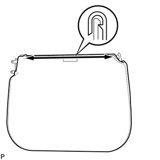
1. REMOVE REAR SEATBACK COVER
|
(a) Remove the 2 screws. |
|
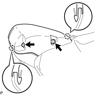
(b) Disengage the 2 claws and remove the rear seatback cover.
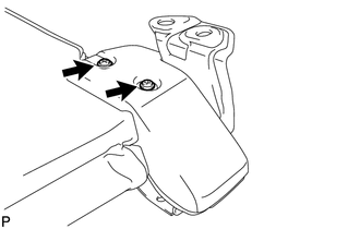
2. REMOVE REAR SEATBACK LOCK COVER
|
(a) Remove the 2 screws and rear seatback lock cover. |
|
3. REMOVE REAR SEAT CUSHION UNDER COVER
|
(a) Remove the screw and rear seat cushion under cover. |
|
4. REMOVE REAR SEAT CUSHION COVER
|
(a) Remove the screw and rear seat cushion cover. |
|
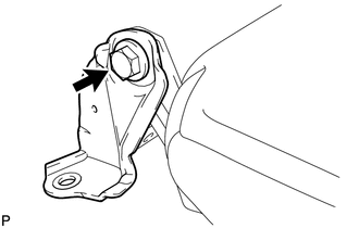
5. REMOVE REAR SEAT HINGE SUB-ASSEMBLY
|
(a) Remove the bolt and rear seat hinge sub-assembly. |
|
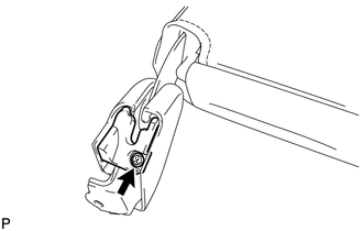
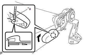
6. REMOVE REAR SEAT LOCK HANDLE
|
(a) Using a screwdriver with its tip wrapped in protective tape, disengage the claw and remove the rear seat lock handle. Text in Illustration
|
|
7. REMOVE REAR SEAT CUSHION SUPPORT BRACKET SUB-ASSEMBLY
|
(a) Using T30 "TORX" socket wrench, remove the bolt. |
|
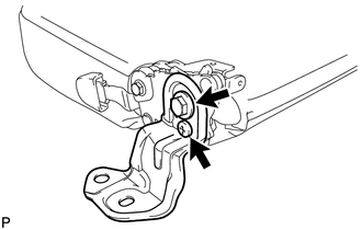
(b) Remove the bolt and rear seat cushion support bracket sub-assembly.
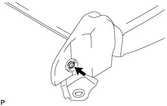
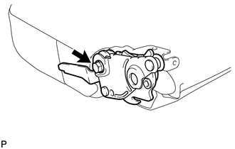
8. REMOVE REAR SEAT LOCK ASSEMBLY
|
(a) Remove the bolt and rear seat lock assembly. |
|
9. REMOVE SEPARATE TYPE REAR SEAT CUSHION COVER
|
(a) Disengage the hook. |
|
(b) Remove the separate type rear seat cushion cover.
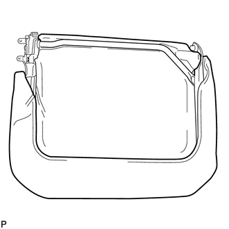
10. REMOVE REAR SEAT CUSHION FRAME SUB-ASSEMBLY
|
(a) Remove the rear seat cushion frame sub-assembly from the rear seat cushion pad. |
|
 Components
COMPONENTS
ILLUSTRATION
ILLUSTRATION
...
 Reassembly
REASSEMBLY
CAUTION / NOTICE / HINT
HINT:
The procedure described below is for the LH side. Use the same procedure for
both the LH and RH sides, unless otherwise specified.
PROCEDURE
1. INSTALL ...
Other materials:
Dtc Check / Clear
DTC CHECK / CLEAR
CHECK DTC
(a) Connect the Techstream to the DLC3.
(b) Turn the ignition switch to ON.
(c) Turn the Techstream on.
(d) Enter the following menus: Chassis / Front Recognition Camera / Trouble Codes.
(e) Check for details of the DTCs.
Click here
CLEAR DTC
(a) Connect the Te ...
Cruise Control Main Switch
Components
COMPONENTS
ILLUSTRATION
Removal
REMOVAL
PROCEDURE
1. REMOVE STEERING PAD ASSEMBLY
(See page )
2. REMOVE CRUISE CONTROL MAIN SWITCH
(a) Disconnect the connector and remove the 2 screws.
(b) Remove the cruise ...
Data List / Active Test
DATA LIST / ACTIVE TEST
1. DATA LIST
HINT:
Using the Techstream to read the Data List allows the values or states of switches,
sensors, actuators and other items to be read without removing any parts. This non-intrusive
inspection can be very useful because intermittent conditions or signals ...
