Toyota Tacoma (2015-2018) Service Manual: Sliding Roof does not Move by Operating Sliding Roof Control Switch
DESCRIPTION
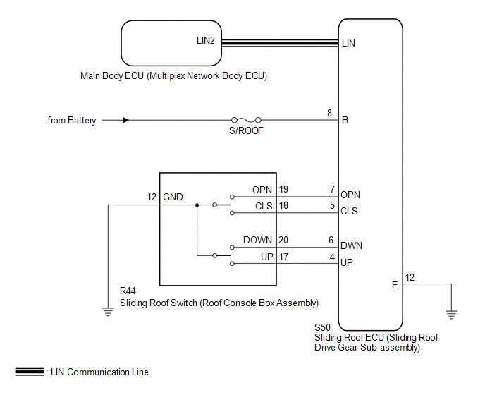
The sliding roof ECU (sliding roof drive gear sub-assembly) receives slide and tilt signals when the sliding roof switch is operated and drives its built-in motor.
WIRING DIAGRAM
CAUTION / NOTICE / HINT
NOTICE:
- Inspect the fuses for circuits related to this system before performing the following inspection procedure.
- When the sliding roof ECU (sliding roof drive gear sub-assembly) is
removed and reinstalled or replaced, the sliding roof ECU (sliding roof
drive gear sub-assembly) must be initialized (See page
.gif) ).
). - The sliding roof system uses the LIN communication system. First, confirm
that there are no malfunctions in the LIN communication system. Refer to
the How to Proceed with Troubleshooting procedure (See page
).
- When a sliding roof ECU (sliding roof drive gear sub-assembly) DTC is output, first perform troubleshooting for the sliding roof ECU (sliding roof drive gear sub-assembly) DTC.
PROCEDURE
|
1. |
READ VALUE USING TECHSTREAM |
(a) Connect the Techstream to the DLC3.
(b) Turn the ignition switch to ON.
(c) Turn the Techstream on.
(d) Enter the following menus: Body Electrical / Sliding Roof / Data List.
(e) Read the Data List according to the display on the Techstream.
Sliding Roof|
Tester Display |
Measurement Item/Range |
Normal Condition |
Diagnostic Note |
|---|---|---|---|
|
Open Switch |
OPEN switch signal/ON or OFF |
ON: OPEN switch pressed OFF: OPEN switch not pressed |
- |
|
Close Switch |
CLOSE switch signal/ON or OFF |
ON: CLOSE switch pressed OFF: CLOSE switch not pressed |
- |
|
Up Switch |
UP switch signal/ON or OFF |
ON: UP switch pressed OFF: UP switch not pressed |
- |
|
Down Switch |
DOWN switch signal/ON or OFF |
ON: DOWN switch pressed OFF: DOWN switch not pressed |
- |
OK:
The Techstream display changes according to switch operation as shown in the table.
| NG | .gif) |
GO TO STEP 3 |
|
.gif)
|
2. |
CHECK HARNESS AND CONNECTOR (SLIDING ROOF ECU - BATTERY AND BODY GROUND) |
(a) Disconnect the S50 sliding roof ECU (sliding roof drive gear sub-assembly) connector.
(b) Measure the voltage according to the value(s) in the table below.
Standard Voltage:
|
Tester Connection |
Condition |
Specified Condition |
|---|---|---|
|
S50-8 (B) - Body ground |
Always |
11 to 14 V |
(c) Measure the resistance according to the value(s) in the table below.
Standard Resistance:
|
Tester Connection |
Condition |
Specified Condition |
|---|---|---|
|
S50-12 (E) - Body ground |
Always |
Below 1 Ω |
| OK | |
REPLACE SLIDING ROOF ECU (SLIDING ROOF DRIVE GEAR SUB-ASSEMBLY) |
| NG | |
REPAIR OR REPLACE HARNESS OR CONNECTOR |
|
3. |
INSPECT SLIDING ROOF SWITCH (ROOF CONSOLE BOX ASSEMBLY) |
|
(a) Remove the sliding roof switch (roof console box assembly) (See page
|
|
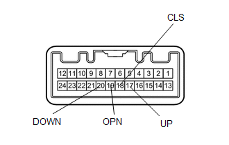
(b) Measure the resistance according to the value(s) in the table below.
Standard Resistance:
|
Tester Connection |
Condition |
Specified Condition |
|---|---|---|
|
17 (UP) - 12 (GND) |
UP switch is pressed |
Below 1 Ω |
|
17 (UP) - 12 (GND) |
UP switch is not pressed |
10 kΩ or higher |
|
20 (DOWN) - 12 (GND) |
DOWN switch is pressed |
Below 1 Ω |
|
20 (DOWN) - 12 (GND) |
DOWN switch is not pressed |
10 kΩ or higher |
|
19 (OPN) - 12 (GND) |
OPEN switch is pressed |
Below 1 Ω |
|
19 (OPN) - 12 (GND) |
OPEN switch is not pressed |
10 kΩ or higher |
|
18 (CLS) - 12 (GND) |
CLOSE switch is pressed |
Below 1 Ω |
|
18 (CLS) - 12 (GND) |
CLOSE switch is not pressed |
10 kΩ or higher |
|
*a |
Component without harness connected (Sliding Roof Switch (Roof Console Box Assembly)) |
| NG | |
REPLACE SLIDING ROOF SWITCH (ROOF CONSOLE BOX ASSEMBLY) |
|
|
4. |
CHECK HARNESS AND CONNECTOR (SLIDING ROOF ECU - SLIDING ROOF SWITCH AND BODY GROUND) |
(a) Disconnect the R44 sliding roof switch (roof console box assembly) connector.
(b) Disconnect the S50 sliding roof ECU (sliding roof drive gear sub-assembly) connector.
(c) Measure the resistance according to the value(s) in the table below.
Standard Resistance:
|
Tester Connection |
Condition |
Specified Condition |
|---|---|---|
|
S50-5 (CLS) - R44-18 (CLS) |
Always |
Below 1 Ω |
|
S50-5 (CLS) - Body ground |
Always |
10 kΩ or higher |
|
S50-7 (OPN) - R44-19 (OPN) |
Always |
Below 1 Ω |
|
S50-7 (OPN) - Body ground |
Always |
10 kΩ or higher |
|
S50-6 (DWN) - R44-20 (DOWN) |
Always |
Below 1 Ω |
|
S50-6 (DWN) - Body ground |
Always |
10 kΩ or higher |
|
S50-4 (UP) - R44-17 (UP) |
Always |
Below 1 Ω |
|
S50-4 (UP) - Body ground |
Always |
10 kΩ or higher |
|
R44-12 (GND) - Body ground |
Always |
Below 1 Ω |
|
S50-12 (E) - Body ground |
Always |
Below 1 Ω |
| OK | |
REPLACE SLIDING ROOF ECU (SLIDING ROOF DRIVE GEAR SUB-ASSEMBLY) |
| NG | |
REPAIR OR REPLACE HARNESS OR CONNECTOR |
 Remote Control System does not Operate
DESCRIPTION
The main body ECU (multiplex network body ECU) receives remote control signals
from the driver door key cylinder or wireless transmitter. Then, the main body ECU
(multiplex network bo ...

Other materials:
Speaker Output Short (B15C3)
DESCRIPTION
This DTC is stored when a malfunction occurs in the speakers.
DTC No.
DTC Detection Condition
Trouble Area
B15C3
A short is detected in the speaker output circuit.
Harness or connector
Speaker
...
Reporting safety defects for U.S. owners
If you believe that your vehicle has a defect which could cause a crash or could
cause injury or death, you should immediately inform the National Highway Traffic
Safety Administration (NHTSA) in addition to notifying Toyota Motor Sales, U.S.A.,
Inc. (Toll-free: 1-800-331-4331).
If NHTSA rece ...
Lost Communication with ECM / PCM "A" (U0100,U0129,U0142,U0151,U0163,U023A,U1104)
DESCRIPTION
The combination meter communicates with the ECM, skid control ECU, power steering
ECU, main body ECU (multiplex network body ECU), airbag sensor assembly, navigation
receiver assembly*1, radio and display receiver assembly*2, Forward recognition
camera*3 and Millimeter wave radar ...
