Toyota Tacoma (2015-2018) Service Manual: Removal
REMOVAL
PROCEDURE
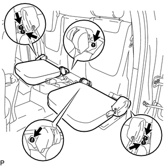
1. REMOVE REAR SEAT CUSHION ASSEMBLY
|
(a) Remove the 6 bolts and 2 rear seat cushion assemblies. |
|
2. REMOVE NO. 4 ROOM PARTITION COVER LH
.gif)
3. REMOVE NO. 4 ROOM PARTITION COVER RH
4. REMOVE NO. 3 ROOM PARTITION COVER
5. REMOVE BACK PANEL GARNISH HOLE PLUG
6. REMOVE BACK PANEL TRIM
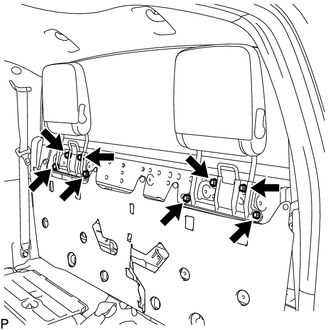
7. REMOVE REAR SEAT HEADREST ASSEMBLY
|
(a) Remove the 8 bolts and 2 rear seat headrest assemblies. |
|
8. REMOVE CHILD RESTRAINT SEAT ANCHOR BRACKET SUB-ASSEMBLY
HINT:
Use the same procedure for each side.
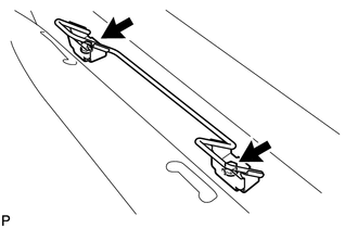
(a) Remove the 2 bolts and child restraint seat anchor bracket sub-assembly.
 Reassembly
REASSEMBLY
CAUTION / NOTICE / HINT
HINT:
The procedure described below is for the LH side. Use the same procedure for
both the LH and RH sides, unless otherwise specified.
PROCEDURE
1. INSTALL ...
 Installation
INSTALLATION
PROCEDURE
1. INSTALL CHILD RESTRAINT SEAT ANCHOR BRACKET SUB-ASSEMBLY
HINT:
Use the same procedure for the side.
(a) Install the child restraint seat anchor bracket sub-assembly with ...
Other materials:
ECU Power Source Circuit
WIRING DIAGRAM
CAUTION / NOTICE / HINT
NOTICE:
Inspect the fuses for circuits related to this system before performing the following
inspection procedure.
PROCEDURE
1.
INSPECT BATTERY
(a) Check the battery voltage.
Standard voltage:
11 to 14 V
NG
...
Portable Player cannot be Registered
CAUTION / NOTICE / HINT
HINT:
Some versions of "Bluetooth" compatible audio players may not function, or the
function may be limited using the navigation receiver assembly, even if the portable
audio player itself can play files (See page ).
PROCEDURE
1.
CHE ...
Data List / Active Test
DATA LIST / ACTIVE TEST
1. DATA LIST
Using the Techstream to read the Data List allows the values or states of switches,
sensors, actuators and other items to be read without removing any parts. This non-intrusive
inspection can be very useful because intermittent conditions or signals may be ...
