Toyota Tacoma (2015-2018) Service Manual: Reassembly
REASSEMBLY
PROCEDURE
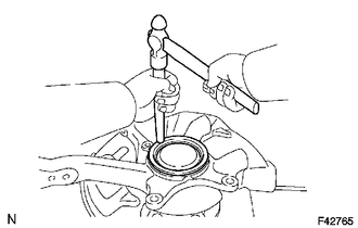
1. INSTALL FRONT AXLE HUB OIL SEAL
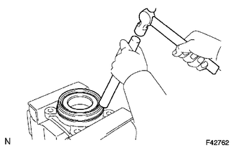
(a) Using a brass bar and a hammer, install a new front axle hub oil seal.
NOTICE:
Do not damage the oil seal.
2. INSTALL FRONT AXLE WITH ABS ROTOR BEARING ASSEMBLY
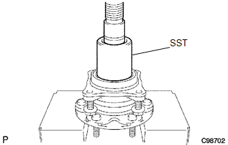
(a) Using SST and a press, install a new bearing onto the front axle hub.
SST: 09649-17010
3. INSTALL FRONT AXLE HUB
.png)
(a) Apply MP grease to a new O-ring.
(b) Install the new O-ring onto the axle hub.
(c) Install the dust cover and axle hub onto the steering knuckle with the 4 bolts.
Torque:
80 N·m {816 kgf·cm, 59 ft·lbf}
4. INSTALL FRONT WHEEL ADJUSTING NUT (for 2WD)
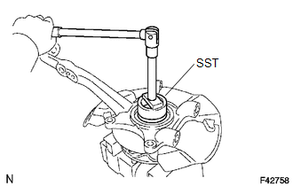
(a) Using SST, install a new front wheel adjusting nut.
SST: 09318-12010
T = 275 N*m{ 2,804 kgf*cm 203 ft.*lbf }
5. INSTALL FRONT AXLE HUB OIL SEAL (for 4WD)
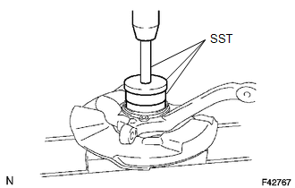
(a) Using SST and a press, install a new front axle hub oil seal.
SST: 09527-17011
SST: 09950-70010
09951-07100
SST: 09951-01000
6. INSTALL KNUCKLE GREASE RETAINER CAP (for 2WD)
(a) Using a brass bar and a hammer, install a new knuckle grease retainer cap.
NOTICE:
Do not damage the knuckle grease retainer cap.
 Disassembly
DISASSEMBLY
PROCEDURE
1. REMOVE KNUCKLE GREASE RETAINER CAP (for 2WD)
(a) Using a screwdriver and hammer, remove the knuckle grease retainer cap.
2. REMOVE FRONT AXLE HUB OIL SEAL (for 4WD)
( ...
 Removal
REMOVAL
PROCEDURE
1. PRECAUTION
NOTICE:
After turning the ignition switch off, waiting time may be required before disconnecting
the cable from the negative (-) battery terminal.
Therefore, mak ...
Other materials:
Brake
General Maintenance
GENERAL MAINTENANCE
PROCEDURE
1. INSPECT BRAKE LINE PIPES AND HOSES
HINT:
Work in a well-lighted area. Turn the front wheels fully to the right or left
before beginning.
(a) Check all the brake lines and hoses for:
Damage
Wear
Deformation
Cracks
...
Lost Communication with Vehicle Dynamics Control Module Missing Message (U012287)
DESCRIPTION
The ECM receives signals from the skid control ECU (brake actuator assembly)
via CAN communication.
DTC No.
DTC Detection Condition
Trouble Area
MIL
Note
U012287
While cruise control main switch ON, co ...
How To Proceed With Troubleshooting
CAUTION / NOTICE / HINT
HINT:
Use this procedure to troubleshoot the engine immobiliser system.
*: Use the Techstream.
PROCEDURE
1.
VEHICLE BROUGHT TO WORKSHOP
NEXT
2 ...
