Toyota Tacoma (2015-2018) Service Manual: Removal
REMOVAL
PROCEDURE
1. PRECAUTION
NOTICE:
After turning the ignition switch off, waiting time may be required before disconnecting the cable from the negative (-) battery terminal.
Therefore, make sure to read the disconnecting the cable from the negative (-) battery terminal notices before proceeding with work.
Click here .gif)
2. DISCONNECT CABLE FROM NEGATIVE BATTERY TERMINAL
NOTICE:
When disconnecting the cable, some systems need to be initialized after the cable is reconnected.
Click here
3. REMOVE FRONT WHEEL
4. DRAIN BRAKE FLUID
NOTICE:
Immediately wash off any brake fluid that comes into contact with painted surfaces.
5. SEPARATE FRONT SPEED SENSOR
|
(a) Remove the bolt and separate the speed sensor front LH. |
|
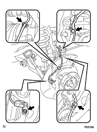
(b) Disengage the 2 clamps.
(c) Remove the bolt and separate the speed sensor wire harness from the steering knuckle.
6. REMOVE FRONT DISC BRAKE CALIPER ASSEMBLY
(a) Remove the bolt and separate the brake tube bracket from the steering knuckle.
|
(b) Using a union nut wrench, disconnect the brake tube from the disc brake cylinder. NOTICE: Use a container to catch the brake fluid as it drains out. |
|
.png)
|
(c) Remove the 2 bolts and disc brake caliper. |
|
.png)
7. REMOVE FRONT DISC
8. REMOVE FRONT AXLE HUB GREASE CAP (for 4WD)
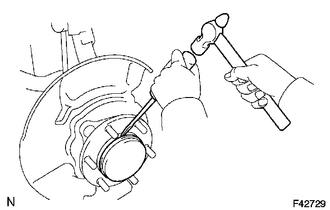
(a) Using a screwdriver and a hammer, remove the front axle hub grease cap.
NOTICE:
Do not damage the axle hub.
9. REMOVE FRONT AXLE HUB NUT (for 4WD)
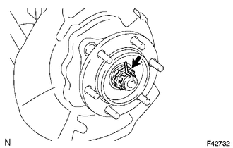
(a) Remove the cotter pin and lock cap.
(b) Remove the front axle hub nut.
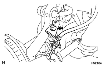
10. SEPARATE FRONT STABILIZER LINK ASSEMBLY
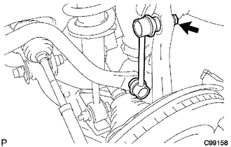
(a) Remove the nut and separate the stabilizer link from the steering knuckle.
HINT:
If the ball joint turns together with the nut, use a hexagon (6 mm) wrench to hold the stud.
11. SEPARATE TIE ROD END SUB-ASSEMBLY
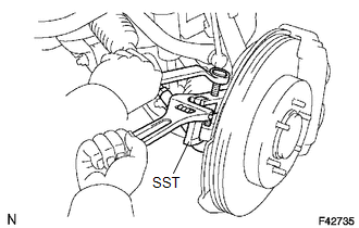
(a) Remove the cotter pin and nut.
(b) Using SST, separate the tie rod end from the steering knuckle.
SST: 09628-62011
12. REMOVE FRONT SUSPENSION LOWER ARM
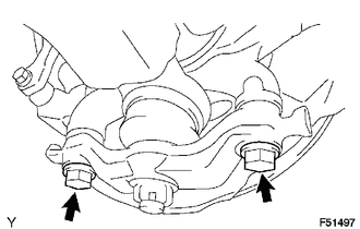
(a) Remove the 2 bolts, and separate the front suspension lower arm from the front axle.
13. SEPARATE FRONT SUSPENSION UPPER ARM
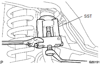
(a) Support the front suspension lower arm with a jack.
(b) Remove the clip and nut.
(c) Using SST, separate the steering knuckle from the front suspension upper arm.
SST: 09628-62011
14. REMOVE FRONT AXLE HUB
(a) for 4WD:
(1) Using a plastic hammer, separate the front axle hub from the front drive shaft.
(b) Remove the front axle hub.
 Reassembly
REASSEMBLY
PROCEDURE
1. INSTALL FRONT AXLE HUB OIL SEAL
(a) Using a brass bar and a hammer, install a new front axle hub oil seal.
NOTICE:
Do not damage the oil seal.
2. INSTALL FRONT AXLE WIT ...
 Installation
INSTALLATION
PROCEDURE
1. INSTALL FRONT AXLE HUB
2. INSTALL FRONT SUSPENSION UPPER ARM
(a) Install a new nut and clip.
Torque:
110 N·m {1122 kgf·cm, 81 ft·lbf}
3. INSTALL FRONT SUSPENSION ...
Other materials:
LVDS Signal Malfunction (from Extension Module) (B1532)
DESCRIPTION
The stereo component tuner assembly and the radio and display receiver assembly
are connected by an LVDS communication line.
This DTC is stored when an LVDS communication error occurs between the stereo
component tuner assembly and the radio and display receiver assembly.
...
Distance Control Switch Circuit
DESCRIPTION
The distance control switch is used to set the distance for vehicle-to-vehicle
distance control mode. The distance control switch is installed in the steering
pad switch assembly. The vehicle-to-vehicle distance set value can be changed by
operating the steering pad switch assembl ...
Registration
REGISTRATION
PROCEDURE
1. DESCRIPTION OF CODE REGISTRATION
(a) w/ Wireless Door Lock Control System:
The key has 2 codes: the key code (immobiliser code) and the wireless code. Both
of these codes need to be registered. For the wireless code registration procedures,
refer to Wireless Door Lo ...
