Toyota Tacoma (2015-2018) Service Manual: Disassembly
DISASSEMBLY
PROCEDURE
1. REMOVE KNUCKLE GREASE RETAINER CAP (for 2WD)
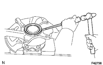
(a) Using a screwdriver and hammer, remove the knuckle grease retainer cap.
2. REMOVE FRONT AXLE HUB OIL SEAL (for 4WD)
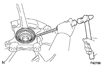
(a) Using a screwdriver and hammer, remove the front axle hub oil seal.
3. REMOVE FRONT WHEEL ADJUSTING NUT (for 2WD)
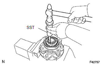
(a) Using SST and a hammer, unstake the front wheel adjusting nut.
SST: 09930-00010
|
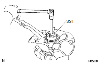
(b) Using SST, remove the front wheel adjusting nut. SST: 09318-12010 |
|
4. REMOVE FRONT AXLE HUB

(a) Remove the 4 bolts and axle hub from the steering knuckle.
(b) Remove the O-ring from the axle hub.
5. REMOVE FRONT AXLE WITH ABS ROTOR BEARING ASSEMBLY
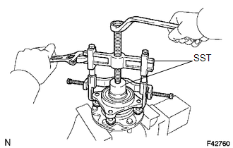
(a) Gently fix the front axle hub in a vise.
(b) Using SST, remove the bearing.
SST: 09710-30021
09710-03051
SST: 09950-40011
09951-04020
09952-04010
09953-04020
09954-04010
09955-04061
09957-04010
09958-04011
6. REMOVE FRONT AXLE HUB OIL SEAL
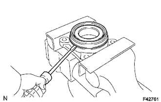
(a) Using a screwdriver, remove the front axle hub oil seal.
 Components
COMPONENTS
ILLUSTRATION
ILLUSTRATION
...
 Reassembly
REASSEMBLY
PROCEDURE
1. INSTALL FRONT AXLE HUB OIL SEAL
(a) Using a brass bar and a hammer, install a new front axle hub oil seal.
NOTICE:
Do not damage the oil seal.
2. INSTALL FRONT AXLE WIT ...
Other materials:
Portable Player cannot be Operated Using In-vehicle Device or Track Information
is not Displayed on In-vehicle Device
PROCEDURE
1.
CHECK USING ANOTHER "Bluetooth" AUDIO COMPATIBLE VEHICLE OF SAME MODEL
(a) Check if track information is displayed normally on another "Bluetooth" audio
compatible vehicle of the same model.
OK:
Track information is displayed no ...
Tires
Replace or rotate tires in accordance with maintenance schedules and treadwear.
■ Checking tire
1. New tread
2. Treadwear indicator
3. Worn tread
The location of treadwear indicators is shown by the “TWI” or “
” marks, etc., molded on the sidewall of each tire.
Check spare ti ...
Disassembly
DISASSEMBLY
PROCEDURE
1. REMOVE REAR AXLE SHAFT SNAP RING
(a) Using a snap ring expander, remove the snap ring.
2. REMOVE REAR AXLE SHAFT
(a) Using SST and press, remove the rear axle shaft.
SST: 09521-25011
SST: 09521-25021
3. REMOVE REAR AXLE BEARING RETAINER INNER
(a) Remove the rear ...
