Toyota Tacoma (2015-2018) Service Manual: Brake
General Maintenance
GENERAL MAINTENANCE
PROCEDURE
1. INSPECT BRAKE LINE PIPES AND HOSES
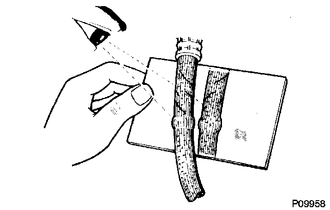
HINT:
Work in a well-lighted area. Turn the front wheels fully to the right or left before beginning.
(a) Check all the brake lines and hoses for:
- Damage
- Wear
- Deformation
- Cracks
- Corrosion
- Leaks
- Bends
- Twists
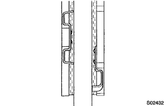
(b) Check all the clamps for tightness and the connections for leakage.
(c) Check if the hoses and lines are not near sharp edges, moving parts and the exhaust system.
(d) Check if the lines are installed pass through the center of the grommets.
2. INSPECT FRONT BRAKE PADS AND DISCS
HINT:
- (See page
.gif) )
) - If a squealing or scraping noise is heard from the brake while driving, check the pad wear indicator.
- If there are traces of the indicator contacting the disc rotor, the disc pad should be replaced.
3. INSPECT REAR BRAKE DRUM
HINT:
See page
4. INSPECT BRAKE FLUID
Fluid:
SAE J1703 or FMVSS No. 116 DOT3
HINT:
- for Hydraulic Brake Booster (See page
)
- for Vacuum Brake Booster (See page )
 Body
Body
General Maintenance
GENERAL MAINTENANCE
PROCEDURE
1. TIGHTEN BOLTS AND NUTS ON CHASSIS AND BODY
(a) Tighten the bolts and nuts on the chassis parts listed below, if necessary.
Front axle ...
 Chassis
General Maintenance
GENERAL MAINTENANCE
PROCEDURE
1. INSPECT STEERING LINKAGE
(a) Check the steering wheel free play (See page
).
(b) Check the steering linkage for looseness or damage.
(1) ...
Other materials:
Disassembly
DISASSEMBLY
CAUTION / NOTICE / HINT
HINT:
The procedure described below is for the LH side. Use the same procedure for
both the LH and RH sides, unless otherwise specified.
PROCEDURE
1. REMOVE REAR SEATBACK COVER
(a) Remove the 2 screws.
...
Reassembly
REASSEMBLY
CAUTION / NOTICE / HINT
HINT:
Use the same procedures for both the LH and RH sides.
The procedure described below is for the LH side.
PROCEDURE
1. INSTALL SIDE TURN SIGNAL LIGHT ASSEMBLY (w/ Side Turn Signal Light)
2. INSTALL OUTER MIRROR COVER (w/o Side Turn Si ...
Diagnostic Trouble Code Chart
DIAGNOSTIC TROUBLE CODE CHART
Smart Key System
DTC Code
Detection Item
See page
B27A1
Open in Driver Side Electrical Antenna Circuit
B27A5
Open in Front Floor Electrical Key Oscillator Circuit
...
