Toyota Tacoma (2015-2018) Service Manual: Precaution
PRECAUTION
1. EXPRESSIONS OF IGNITION SWITCH
HINT:
The type of ignition switch used on this model differs according to the specifications of the vehicle. The expressions listed in the table below are used in this section.
|
Expression |
Ignition Switch (Position) |
Engine Switch (Condition) |
|---|---|---|
|
Ignition Switch off |
LOCK |
Off (Lock) |
|
Ignition Switch ACC |
ACC |
On (ACC) |
|
Ignition Switch ON |
ON |
On (IG) |
|
Engine Start |
START |
On (Start) |
2. CAN COMMUNICATION SYSTEM TROUBLESHOOTING
(a) Because the order of diagnosis is important to allow correct diagnosis, make sure to begin troubleshooting using How to Proceed with Troubleshooting when CAN communication system related DTCs are output.
Click here .gif)
3. PRECAUTION FOR STEERING SYSTEM HANDLING
(a) Be careful when replacing parts. Incorrect replacement could affect the performance of the steering system and result in hazardous driving.
4. PRECAUTION FOR SRS AIRBAG SYSTEM HANDLING
(a) This vehicle is equipped with a Supplemental Restraint System (SRS) which includes parts such as airbags for the driver and front passenger. Failure to carry out service operations in the correct sequence could cause unexpected SRS deployment during servicing and may cause a serious accident. Before servicing (including removal or installation of parts, inspection or replacement), be sure to read Precaution for SRS.
Click here
5. BUS LINE REPAIR
(a) After repairing a bus line with solder, wrap the repaired part with electrical tape.
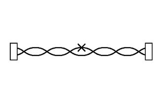
NOTICE:
- The CANL bus line and CANH bus line must be installed together at all times.
- When installing, make sure that these lines are twisted, because CAN bus lines are likely to be influenced by electrical noise if the bus lines are not twisted.
- Leave approximately 80 mm (3.15 in.) loose in the twisted wires around the connector.
- When repairing the CAN bus lines, do not change the length of the lines. (Make sure that the length of the CANH bus line and CANL bus line are the same.)
(b) Do not use bypass wiring between connectors.
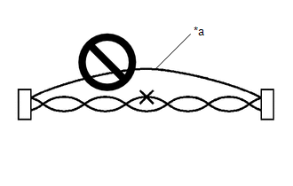 Text in Illustration
|
*a |
Bypass Wire |
NOTICE:
- The ability of the twisted bus lines to resist interference will be lost if bypass wiring is used.
- Do not use a twisted pair of wires for bypass wiring.
6. CONNECTOR HANDLING
(a) When checking resistance with a tester, insert the tester probes from the backside (harness side) of the connector.
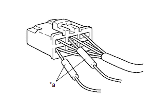 Text in Illustration
|
*a |
Tester Probe |
(b) Use service wires to check the connector if it is impossible to check continuity from the rear of the connector.
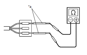 Text in Illustration
|
*a |
Service Wire |
7. PRECAUTIONS FOR INSPECTING OR REPLACING CAN JUNCTION CONNECTOR
(a) If the CAN junction connector is removed from the vehicle for inspection or replacement, make sure to install the CAN junction connector and all wire harnesses to their original locations with tape and the clamps.
8. PRECAUTIONS WHEN REPLACING A GATEWAY FUNCTION EQUIPPED ECU (SUB BUS MONITOR ECU OR CENTRAL GATEWAY ECU (NETWORK GATEWAY ECU)) WITH A USED ONE FROM ANOTHER VEHICLE
(a) When a gateway function equipped ECU (main body ECU (multiplex network body ECU) or central gateway ECU (network gateway ECU)) that was previously installed on another vehicle is used as a replacement part, it is necessary to initialize the connection information stored in the ECU.
Click here
NOTICE:
If the connection information stored in a gateway function equipped ECU that was previously installed on another vehicle is different from the actual ECUs and sensors connected to the corresponding bus, communication DTCs will be detected.
HINT:
It is not necessary to perform initialization of a gateway monitoring ECU (sub bus monitoring ECU) when using a sub bus monitoring ECU which was installed to another vehicle with the same sub bus configuration.
9. PRECAUTIONS FOR WHEN GATEWAY FUNCTION EQUIPPED ECU (SUB BUS MONITOR ECU OR CENTRAL GATEWAY ECU (NETWORK GATEWAY ECU)) DETECTS COMMUNICATION DTCS FOR ECUS NOT CONNECTED TO THE ECU
(a) Refer to Precautions When Replacing a Gateway Function Equipped ECU (Sub Bus Monitor ECU or Central Gateway ECU (Network Gateway ECU)) with a Used One from Another Vehicle and initialize the connection information of the ECU.
(b) Clear the DTCs and check that no DTCs are output.
10. DIFFERENCE BETWEEN GENUINE NAVIGATION RECEIVERS/RADIO AND DISPLAY RECEIVERS AND OPTIONAL NAVIGATION RECEIVERS/RADIO AND DISPLAY RECEIVERS
(a) Some optional navigation receivers/radio and display receivers are available as CAN compatible devices. Be aware that some optional navigation receivers/radio and display receivers do not have the same diagnostic features or characteristics of genuine navigation receivers/radio and display receivers.
NOTICE:
- Optional navigation receivers/radio and display receivers receive data from the CAN communication system. However, most optional navigation receivers/radio and display receivers do not send signals to the CAN bus main line.
- Optional navigation receivers/radio and display receivers will not be displayed on the "CAN Bus Check" screen of the Techstream.
- When checking for DTCs using the Techstream, DTCs for optional navigation receivers/radio and display receivers will not be displayed on the Techstream.
 Parts Location
PARTS LOCATION
ILLUSTRATION
*A
for Hydraulic Brake Booster
*B
for Vacuum Brake Booster
*C
w/ Toyota Safety Sense P
...
 System Diagram
SYSTEM DIAGRAM
1. OVERALL CAN BUS DIAGRAM
(a) The CAN communication system is composed of 4 buses.
CAN Main Bus Line
Terminating Resistor
...
Other materials:
Precaution
PRECAUTION
1. INITIALIZATION
NOTICE:
If the ECM is replaced, register the ECU communication ID for Engine
Immobiliser System (See page ).
Perform Registration (VIN registration) when replacing the ECM (See
page ).
HINT:
The engine learned value cannot be rese ...
ABS Warning Light Remains ON
DESCRIPTION
The skid control ECU (brake actuator assembly) is connected to the combination
meter assembly via CAN communication.
If any of the following is detected, the ABS warning light remains on:
The skid control ECU (brake actuator assembly) connectors are disconnected
from the ...
Removal
REMOVAL
PROCEDURE
1. REMOVE INSTRUMENT PANEL SUB-ASSEMBLY
(See page
)
2. REMOVE NO. 3 HEATER TO REGISTER DUCT
3. REMOVE INSTRUMENT PANEL WIRE ASSEMBLY
(a) Using a screwdriver with its tip wrapped in protective tape, release
the 3 airbag connector locks.
Text in Illustr ...
