Toyota Tacoma (2015-2018) Service Manual: Removal
REMOVAL
PROCEDURE
1. REMOVE INSTRUMENT PANEL SUB-ASSEMBLY
(See page .gif) )
)
2. REMOVE NO. 3 HEATER TO REGISTER DUCT
3. REMOVE INSTRUMENT PANEL WIRE ASSEMBLY
|
(a) Using a screwdriver with its tip wrapped in protective tape, release the 3 airbag connector locks. Text in Illustration
|
|
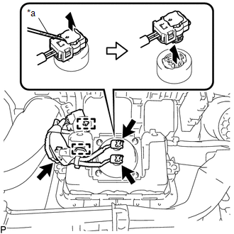
(b) Disconnect the 3 airbag connectors.
NOTICE:
When handling the airbag connector, take care not to damage the airbag wire harness.
(c) Disengage the 2 clamps to remove the instrument panel wire assembly.
4. REMOVE INSTRUMENT PANEL PASSENGER AIRBAG ASSEMBLY WITHOUT DOOR
|
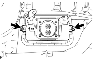
(a) Remove the 2 screws. |
|
|
(b) Disengage the 3 hooks (A). Text in Illustration
|
|
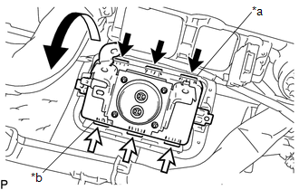
(c) Disengage the 3 hooks (B) to remove the instrument panel passenger airbag assembly without door from the instrument panel.
 On-vehicle Inspection
ON-VEHICLE INSPECTION
PROCEDURE
1. INSPECT INSTRUMENT PANEL PASSENGER AIRBAG ASSEMBLY WITHOUT DOOR (for Vehicle
not Involved in Collision)
(a) Perform a diagnostic system check (See pa ...
 Disposal
DISPOSAL
CAUTION / NOTICE / HINT
CAUTION:
Before performing pre-disposal deployment of any SRS part, review and closely
follow all applicable environmental and hazardous material regulations. Pre ...
Other materials:
Remote Up / Down Function does not Operate
DESCRIPTION
When the ignition switch is ON, the power window regulator master switch assembly
sends remote up/down signals to each power window regulator motor assembly via the
LIN communication line.
WIRING DIAGRAM
CAUTION / NOTICE / HINT
NOTICE:
The power window control system u ...
Initialization
INITIALIZATION
1. RESET MEMORY
NOTICE:
Perform Reset Memory (AT initialization) when replacing the automatic
transmission assembly, transmission valve body assembly or any of the shift
solenoid valves.
Reset Memory can be performed only with the Techstream.
HINT:
The E ...
Removal
REMOVAL
PROCEDURE
1. REMOVE MILLIMETER WAVE RADAR WIRE
(a) for Type A:
(1) Disconnect the 2 connectors.
(2) Using a clip remover, disengage the 4 clamps to remove the millimeter
wave radar wire.
(b) for Type B:
(1) Disc ...
