Toyota Tacoma (2015-2018) Service Manual: ABS Warning Light Remains ON
DESCRIPTION
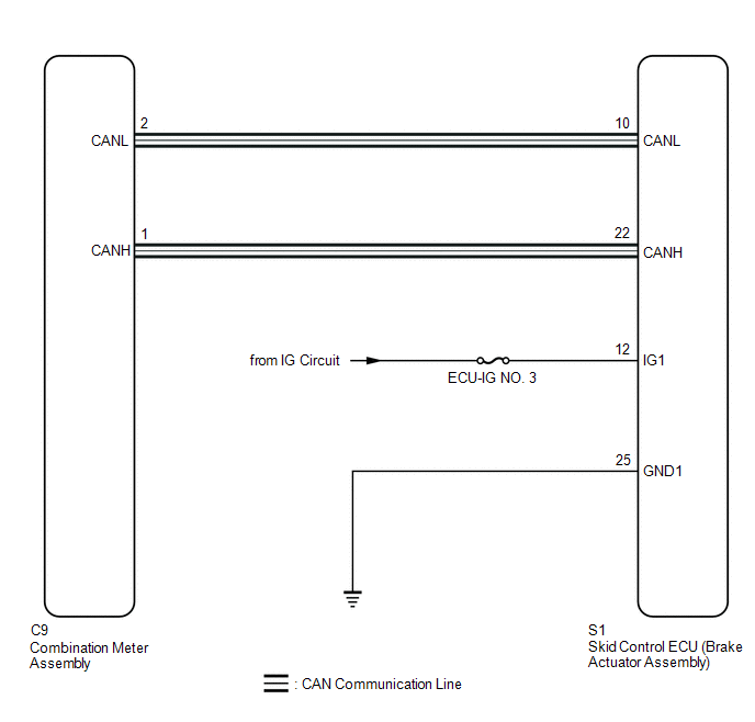
The skid control ECU (brake actuator assembly) is connected to the combination meter assembly via CAN communication.
If any of the following is detected, the ABS warning light remains on:
- The skid control ECU (brake actuator assembly) connectors are disconnected from the skid control ECU (brake actuator assembly).
- There is a malfunction in the skid control ECU (brake actuator assembly) internal circuit.
- There is an open in the harness between the combination meter assembly and the skid control ECU (brake actuator assembly).
- The ABS control system is defective.
- w/ Rear Differential Lock:
The rear differential is locked.
HINT:
In some cases, the Techstream cannot be used when the skid control ECU (brake actuator assembly) is abnormal.
WIRING DIAGRAM
CAUTION / NOTICE / HINT
NOTICE:
- When replacing the skid control ECU (brake actuator assembly), perform
zero point calibration and store system information (See page
.gif) ).
).
- Inspect the fuses for circuits related to this system before performing the following inspection procedure.
PROCEDURE
|
1. |
CHECK CAN COMMUNICATION SYSTEM |
(a) Check if CAN communication system DTCs are output (See page
).
|
Result |
Proceed to |
|---|---|
|
DTC is not output |
A |
|
DTC is output |
B |
| B | .gif) |
CHECK CAN COMMUNICATION SYSTEM |
|
.gif)
|
2. |
CHECK IF BRAKE ACTUATOR ASSEMBLY CONNECTOR IS SECURELY CONNECTED |
(a) Check if the skid control ECU (brake actuator assembly) connector is securely connected.
OK:
The connector is securely connected.
| NG | |
CONNECT CONNECTOR TO BRAKE ACTUATOR ASSEMBLY CORRECTLY |
|
|
3. |
INSPECT BATTERY |
(a) Check the battery voltage.
Standard voltage:
11 to 14 V
| NG | |
CHECK OR REPLACE CHARGING SYSTEM OR BATTERY |
|
|
4. |
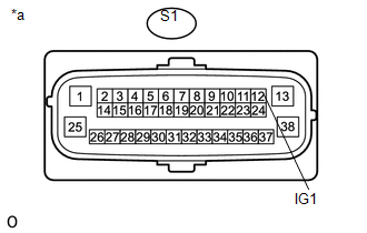
CHECK TERMINAL VOLTAGE (IG1 TERMINAL) |
|
(a) Disconnect the S1 skid control ECU (brake actuator assembly) connector. |
|
(b) Turn the ignition switch to ON.
(c) Measure the voltage according to the value(s) in the table below.
Standard Voltage:
|
Tester Connection |
Switch Condition |
Specified Condition |
|---|---|---|
|
S1-12 (IG1) - Body ground |
Ignition switch ON |
11 to 14 V |
|
*a |
Front view of wire harness connector (to Skid Control ECU [Brake Actuator Assembly]) |
| NG | |
REPAIR OR REPLACE HARNESS OR CONNECTOR (IG1 CIRCUIT) |
|
|
5. |
CHECK HARNESS AND CONNECTOR (GND1 TERMINAL) |
(a) Turn the ignition switch off.
|
(b) Measure the resistance according to the value(s) in the table below. Standard Resistance:
|
|
.png)
|
Result |
Proceed to |
|---|---|
|
OK (w/ Rear Differential Lock) |
A |
|
OK (w/o Rear Differential Lock) |
B |
|
NG |
C |
| B | |
GO TO STEP 7 |
| C | |
REPAIR OR REPLACE HARNESS OR CONNECTOR (GND1 CIRCUIT) |
|
|
6. |
CHECK FOR DIFFERENTIAL SYSTEM |
(a) Reconnect the S1 skid control ECU (brake actuator assembly) connector.
(b) Connect the Techstream to the DLC3.
(c) Turn the ignition switch to ON.
(d) Turn the Techstream on.
(e) Enter the following menus: Powertrain / Four Wheel Drive / Trouble Codes.
(f) Check for DTCs.
Result|
Result |
Proceed to |
|---|---|
|
DTCs are not output |
A |
|
DTCs are output |
B |
| B | |
GO TO DIFFERENTIAL SYSTEM (DIAGNOSTIC TROUBLE CODE CHART) |
|
|
7. |
READ VALUE USING TECHSTREAM (ABS WARNING LIGHT) |
(a) Reconnect the S1 skid control ECU (brake actuator assembly) connector.
(b) Connect the Techstream to the DLC3.
(c) Turn the ignition switch to ON.
(d) Turn the Techstream on.
(e) Enter the following menus: Chassis / ABS/VSC/TRAC / Data List.
(f) According to the display on the Techstream, read the Data List.
ABS/VSC/TRAC|
Tester Display |
Measurement Item |
Range |
Normal Condition |
Diagnostic Note |
|---|---|---|---|---|
|
ABS Warning Light |
ABS warning light |
OFF or ON |
OFF: Warning light off ON: Warning light on |
- |
(g) Check the Techstream display condition of the ABS warning light.
Result|
Result |
Proceed to |
|---|---|
|
Display of the Data List remains OFF |
A |
|
Display of the Data List remains ON |
B |
| A | |
INSPECT METER / GAUGE SYSTEM |
| B | |
REPLACE BRAKE ACTUATOR ASSEMBLY |
 ABS Warning Light does not Come ON
DESCRIPTION
The skid control ECU (brake actuator assembly) is connected to the combination
meter assembly via CAN communication.
WIRING DIAGRAM
Refer to ABS Warning Light Remains ON (See page
) ...
 Brake Warning Light Remains ON
DESCRIPTION
The skid control ECU (brake actuator assembly) is connected to the combination
meter assembly via CAN communication.
If any of the following is detected, the brake warning light remain ...
Other materials:
On-vehicle Inspection
ON-VEHICLE INSPECTION
PROCEDURE
1. INSPECT CURTAIN SHIELD AIRBAG ASSEMBLY (for Vehicle not Involved in Collision)
(a) Perform a diagnostic system check (See page
).
(b) With the curtain shield airbag assembly installed on the vehicle,
perform a visual check. If there are any def ...
On-vehicle Inspection
ON-VEHICLE INSPECTION
PROCEDURE
1. INSPECT CURTAIN SHIELD AIRBAG ASSEMBLY (for Vehicle not Involved in Collision)
(a) Perform a Diagnostic System Check (See page
).
(b) With the curtain shield airbag installed on the vehicle, perform
a visual check. If any of the defects mention ...
Dtc Check / Clear
DTC CHECK / CLEAR
CHECK DTC
(a) Connect the Techstream to the DLC3.
(b) Turn the ignition switch to ON.
(c) Turn the Techstream on.
(d) Enter the following menus: Chassis / Front Recognition Camera / Trouble Codes.
(e) Check for details of the DTCs.
Click here
CLEAR DTC
(a) Connect the Te ...
