Toyota Tacoma (2015-2018) Service Manual: Parts Location
PARTS LOCATION
ILLUSTRATION
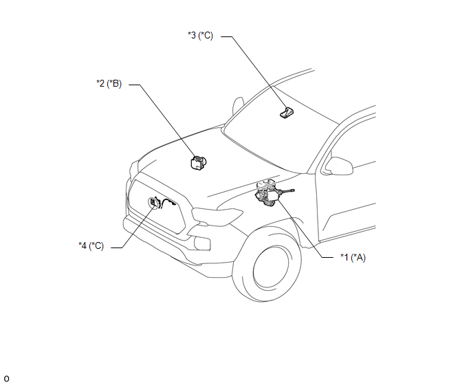
|
*A |
for Hydraulic Brake Booster |
*B |
for Vacuum Brake Booster |
|
*C |
w/ Toyota Safety Sense P |
- |
- |
|
*1 |
BRAKE BOOSTER ASSEMBLY (SKID CONTROL ECU) |
*2 |
BRAKE ACTUATOR ASSEMBLY (SKID CONTROL ECU) |
|
*3 |
FORWARD RECOGNITION CAMERA |
*4 |
MILLIMETER WAVE RADAR SENSOR ASSEMBLY |
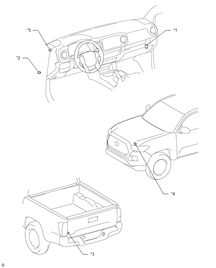
ILLUSTRATION
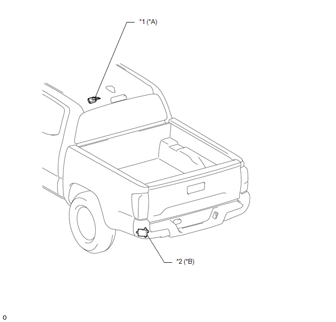
|
*A |
w/ Tire Pressure Warning System and Tire Inflation Pressure Display Function |
*B |
w/ Blind Spot Monitor System |
|
*1 |
DOOR CONTROL AND TIRE PRESSURE MONITORING SYSTEM RECEIVER ASSEMBLY |
*2 |
BLIND SPOT MONITOR SENSOR LH |
ILLUSTRATION
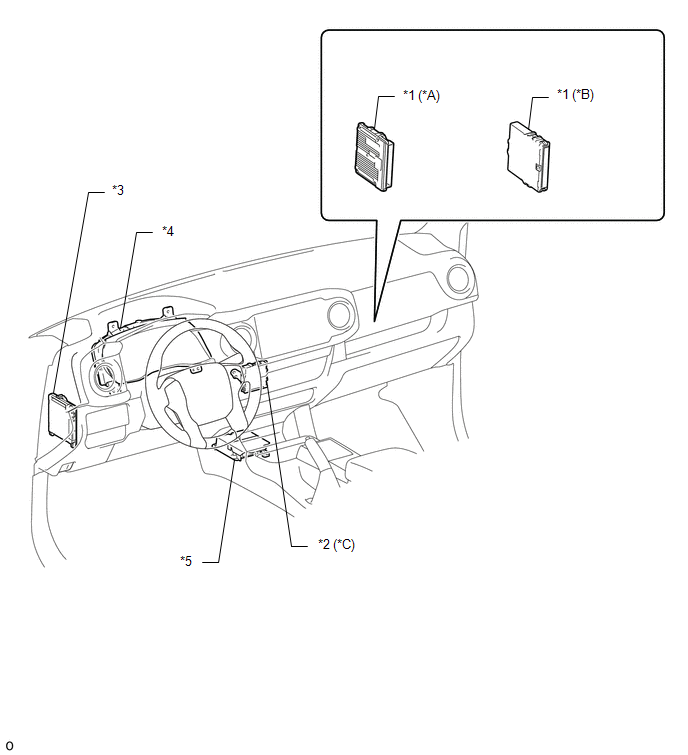
|
*A |
for 2GR-FKS |
*B |
for 2TR-FE |
|
*C |
w/ Intuitive Parking Assist System |
- |
- |
|
*1 |
ECM |
*2 |
CLEARANCE WARNING ECU ASSEMBLY |
|
*3 |
MAIN BODY ECU (MULTIPLEX NETWORK BODY ECU) |
*4 |
COMBINATION METER ASSEMBLY |
|
*5 |
AIRBAG SENSOR ASSEMBLY |
- |
- |
ILLUSTRATION
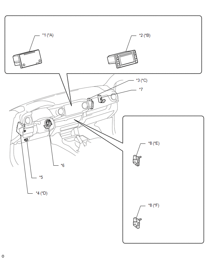
|
*A |
for Navigation Receiver Type |
*B |
for Radio and Display Type |
|
*C |
for 4WD |
*D |
w/ Smart Key System |
|
*E |
for Automatic Air Conditioning System |
*F |
for Manual Air Conditioning System |
|
*1 |
NAVIGATION RECEIVER ASSEMBLY |
*2 |
RADIO AND DISPLAY RECEIVER ASSEMBLY |
|
*3 |
4 WHEEL DRIVE CONTROL ECU |
*4 |
CERTIFICATION ECU (SMART KEY ECU ASSEMBLY) |
|
*5 |
DLC3 |
*6 |
SPIRAL CABLE WITH SENSOR SUB-ASSEMBLY |
|
*7 |
CENTRAL GATEWAY ECU (NETWORK GATEWAY ECU) |
*8 |
AIR CONDITIONING AMPLIFIER ASSEMBLY |
ILLUSTRATION
|
*1 |
NO. 1 CAN JUNCTION CONNECTOR |
*2 |
NO. 2 CAN JUNCTION CONNECTOR |
|
*3 |
NO. 4 CAN JUNCTION CONNECTOR |
*4 |
NO. 5 CAN JUNCTION CONNECTOR |
|
*5 |
NO. 6 CAN JUNCTION CONNECTOR |
- |
- |

 Precaution
PRECAUTION
1. EXPRESSIONS OF IGNITION SWITCH
HINT:
The type of ignition switch used on this model differs according to the specifications
of the vehicle. The expressions listed in the table below ...
Other materials:
While Alarm is Armed, Engine Hood is opened but Alarm does not Sound
DESCRIPTION
A situation in which the alarm is armed but does not sound when the hood is opened
can be caused when the main body ECU (multiplex network body ECU) cannot detect
whether the hood courtesy switch is open or closed.
If the alarm does not sound, there may be a malfunction in the hood ...
Zero Point Calibration of Yaw Rate Sensor Undone (C1210,C1336)
DESCRIPTION
The skid control ECU (brake actuator assembly) receives signals from the yaw
rate and acceleration sensor (airbag sensor assembly) via the CAN communication
system.
The airbag sensor assembly has a built-in yaw rate and acceleration sensor and
detects the vehicle condition. If th ...
Installation
INSTALLATION
PROCEDURE
1. SET NO. 1 CYLINDER TO TDC/COMPRESSION
2. INSTALL CAMSHAFT TIMING GEAR BOLT
NOTICE:
There are different types of camshaft timing gear bolts. Make sure to check the
identification mark to determine the tightening torque.
*a
Identification Ma ...
