Toyota Tacoma (2015-2018) Service Manual: On-vehicle Inspection
ON-VEHICLE INSPECTION
PROCEDURE
1. CHECK BRAKE BOOSTER ASSEMBLY
|
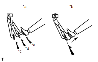
(a) Airtightness check. Text in Illustration
(1) Start the engine and stop it after 1 or 2 minutes. Slowly depress the brake pedal several times. If the pedal can be depressed to the floor the first time, but cannot be depressed to the floor the second and third time, the booster is airtight. (2) Depress the brake pedal while the engine is running and stop the engine with the brake pedal depressed. If there is no change in the pedal reserve distance while holding the pedal for 30 seconds, the booster is airtight. |
|
|
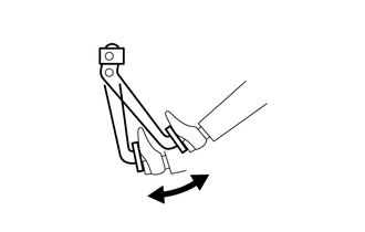
(b) Operation check. (1) Depress the brake pedal several times with the ignition switch off and check that there is no change in the pedal reserve distance when the pedal is depressed. (2) Depress and hold down the pedal, and then start the engine. If the pedal goes down slightly, the operation is normal. |
|
 Components
COMPONENTS
ILLUSTRATION
...
 Removal
REMOVAL
CAUTION / NOTICE / HINT
NOTICE:
Release the vacuum from booster by depressing the brake pedal several times.
Then remove the brake master cylinder from brake booster.
PROCEDURE
1. PRECAU ...
Other materials:
Reassembly
REASSEMBLY
PROCEDURE
1. INSTALL UN-LOCK WARNING SWITCH ASSEMBLY (w/o Smart Key System)
(a) Engage the 2 claws to install the un-lock warning switch assembly to the
upper steering column bracket assembly.
2. INSTALL IGNITION SWITCH LOCK CYLINDER ASSEMBLY (w/o Smart Key System)
(a) T ...
How To Proceed With Troubleshooting
CAUTION / NOTICE / HINT
HINT:
Use this procedure to troubleshoot the engine immobiliser system.
*: Use the Techstream.
PROCEDURE
1.
VEHICLE BROUGHT TO WORKSHOP
NEXT
2 ...
Installation
INSTALLATION
CAUTION / NOTICE / HINT
CAUTION:
Some of these service operations affect the SRS airbag system. Read the precautionary
notices concerning the SRS airbag system before servicing (See page
).
HINT:
Use the same procedure for both the RH and LH sides.
The procedure des ...
