Toyota Tacoma (2015-2018) Service Manual: Rear Leaf Spring
Components
COMPONENTS
ILLUSTRATION
Disassembly
DISASSEMBLY
PROCEDURE
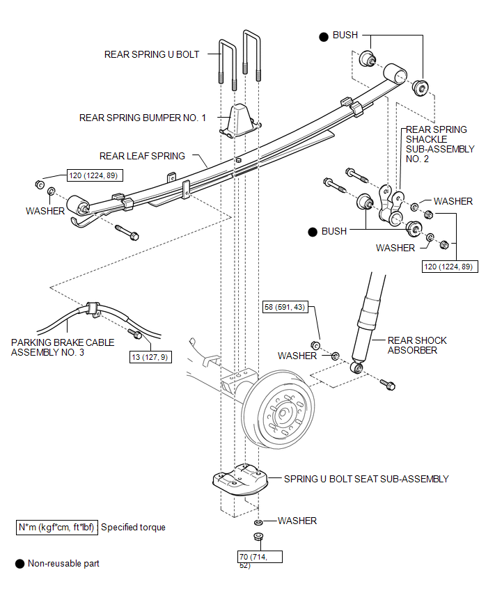
1. REMOVE BUSH
(a) Fix the spring in a vise.
(b) Using a hack saw, cut both ends off the bushes.
|
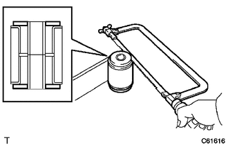
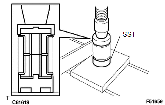
(c) Using SST and a press, press out the 2 bushes. SST: 09950-60010 09951-00350 SST: 09950-70010 09951-07100 |
|
|
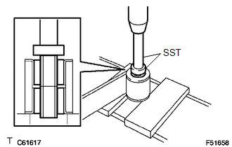
(d) Using a chisel and hammer, tap out the 2 outer tubes. |
|
Reassembly
REASSEMBLY
PROCEDURE
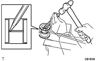
1. INSTALL BUSH
(a) Using SST and a press, press in 2 new bushes.
SST: 09710-28012
09710-07062
SST: 09710-30041
09710-03211
Removal
REMOVAL
PROCEDURE
1. REMOVE REAR WHEEL
2. REMOVE SPARE TIRE
3. SEPARATE REAR SHOCK ABSORBER
|
(a) Support the rear axle housing. |
|
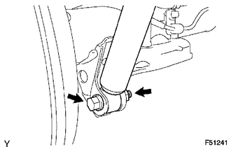
(b) Remove the bolt, nut and washer.
(c) Separate the shock absorber from the rear axle housing.
4. SEPARATE PARKING BRAKE CABLE ASSEMBLY NO. 3
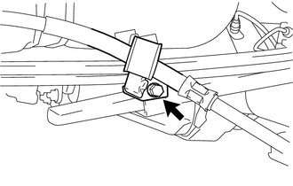
(a) Remove the bolt, then separate the parking brake cable.
5. REMOVE REAR SPRING U BOLT
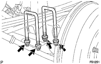
(a) Remove the 4 nuts and 4 washers.
(b) Remove the spring seat and 2 U-bolts.
(c) Remove the spring bumper.
6. REMOVE REAR LEAF SPRING
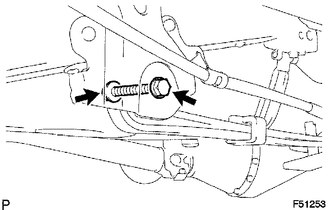
(a) Remove the nut, washer and through bolt.
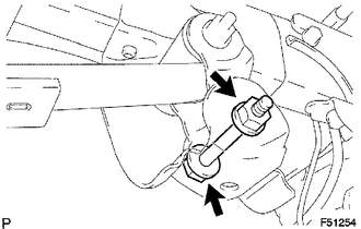
|
(b) Remove the nut, washer and through bolt. NOTICE: Be careful not to drop the spring when removing the through bolt. |
|
(c) Remove the spring.
7. REMOVE REAR SPRING SHACKLE SUB-ASSEMBLY NO. 2
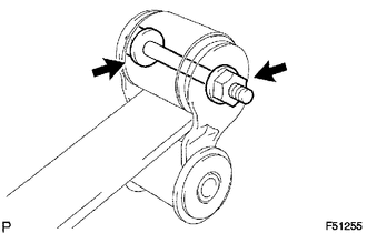
(a) Remove the nut, washer, through bolt and shackle.
Installation
INSTALLATION
PROCEDURE
1. INSTALL REAR SPRING SHACKLE SUB-ASSEMBLY NO. 2
.png)
(a) Install the shackle with the through bolt, washer and nut.
2. INSTALL REAR LEAF SPRING
(a) Place the spring in the rear axle housing.
(b) Align the hole of the rear axle housing with the head of the spring center bolt.
|
(c) Install the through bolt, washer and nut. |
|
.png)
|
(d) Install the through bolt, washer and nut. |
|
.png)
3. INSTALL REAR SPRING U BOLT
(a) Install the spring bumper.
|
(b) Install the spring seat, 2 U-bolts, 4 washers and 4 nuts. Torque: 70 N·m {714 kgf·cm, 52 ft·lbf} HINT: Tighten the U-bolts until the lengths of all the U-bolts under the spring seat are the same. |
|
.png)
4. INSTALL PARKING BRAKE CABLE ASSEMBLY NO. 3
.png)
(a) Install the parking brake cable with the bolt.
Torque:
13 N·m {127 kgf·cm, 9 ft·lbf}
5. INSTALL REAR SHOCK ABSORBER
.png)
(a) Install the shock absorber with the bolt, nut and washer.
6. INSTALL REAR WHEEL
Torque:
113 N·m {1152 kgf·cm, 83 ft·lbf}
7. STABILIZE REAR SUSPENSION
(a) Lower the vehicle.
(b) Bounce the vehicle up and down several times to stabilize the suspension.
8. FULLY TIGHTEN REAR SUSPENSION
(a) Tighten the nuts and bolts of the rear suspension parts.
Torque:
|
Part Tightened |
N*m |
kgf*cm |
ft.*lbf |
|---|---|---|---|
|
Rear LH spring x Rear spring shackle |
120 |
1224 |
89 |
|
Rear LH spring x Frame |
120 |
1224 |
89 |
|
Rear spring shackle x Frame |
120 |
1224 |
89 |
|
Rear shock absorber x Rear axle housing |
58 |
591 |
43 |
9. INSTALL SPARE TIRE
 Adjustment
ADJUSTMENT
CAUTION / NOTICE / HINT
NOTICE:
For vehicles equipped with VSC, if the wheel alignment has been adjusted, and
if suspension or underbody components have been removed/installed or repla ...
 Rear Shock Absorber
Components
COMPONENTS
ILLUSTRATION
Inspection
INSPECTION
PROCEDURE
1. INSPECT REAR SHOCK ABSORBER
(a) Compress and extend the shock absorber rod and check that there is no abnormal
re ...
Other materials:
Precaution
PRECAUTION
1. EXPRESSIONS OF IGNITION SWITCH
HINT:
The type of ignition switch used on this model differs according to the specifications
of the vehicle. The expressions listed in the table below are used in this section.
Expression
Ignition Switch
(Position)
...
Data List / Active Test
DATA LIST / ACTIVE TEST
1. DATA LIST
HINT:
Using the Techstream to read the Data List allows the values or states of switches,
sensors, actuators and other items to be read without removing any parts. This non-intrusive
inspection can be very useful because intermittent conditions or signals ...
Speaker Output Short (B15C3)
DESCRIPTION
This DTC is stored when a malfunction occurs in the speakers.
DTC No.
DTC Detection Condition
Trouble Area
B15C3
A short is detected in the speaker output circuit.
Harness or connector
Speaker
...
